background image

1

2

4

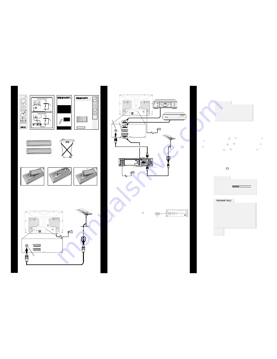
SUPPLIED ACCESORIES

Remote

Control

Typical

Connections

FITTING THE BATTERIES

2

3

TYPICAL CONNECTIONS

TYPICAL CONNECTIONS (Continued)

Mains Socket Outlet

AC 220~240 V, 50 Hz

Mains Socket Outlet

AC 220~240 V, 50 Hz

AV/TERMINAL

(EXT-1)

BACK OF TV

ANT.

EXT.2

EXT.1

DVD PLAYER

DECODER

Scart Lead

(Not supplied)

Scart Lead

(Not supplied)

AV/TERMINAL

(EXT-2)

Aerial IN

Scart Lead

(Not supplied)

Aerial Lead

(Not supplied)

Aerial

(Not supplied)

Aerial IN

Audio/Video

BACK OF VCR

RF OUT

Operation

Manual

Quick Start

Guide

+

-

+

-

R03 ("AAA" size) Dry Batteries

1. With your thumb

nail, pull up the

slit as shown.

2. Insert the two

batteries as shown.

3. Replace the battery

cover.

A SCART lead (not supplied) is recommended for use with this TV, to

obtain the best communication between your TV and VCR, refer

to page 24 of the operation manual.

Check List:

• Is the TV connected to the mains?

• Is the aerial connected to the TV?

TURN TV ON FOR THE FIRST TIME

TV set

Main power button

1

3

2

Aerial IN

Back of TV

Aerial

(Not supplied)

Aerial Lead

(Not supplied)

ANT.

EXT.2

EXT.1

Mains Socket Outlet

AC 220~240 V, 50 Hz

INITIAL SETTINGS

The message “

” will be

displayed when you turn on your TV for the first time.

PLEASE CHECK ANTENNA CABLE!

Note:

1-

LANGUAGE

2-

COUNTRY

3-

START

APS

APS

APS APS IS RUNNING PLEASE WAIT

APS

PROGRAM

TABLE

APS

If you connect Video Recorder to your TV via antenna input

(ANT socket); toÊtune the VCR channel automaticallyÊyou must

set the VCR in play mode before you startAPS. (Please use a PAL

/ SECAM Video Cassette).

Select

with

button, then press the

button to select a menu language.

Select

with

button, then press the

button to select the correct country.

Select

with

button, then press the “ ” button

to start

.

, (Automatic Programming System) automatically

programmes the received channels in your TV’s programme

numbers. During

, “

message will be displayed. After

is finalized, the “

” appears.

To cancel

, press the “ ” button.

“ ” or “ ”

“ ” or

“ ”

“ ” or “

“ ” or “

“ ” or “

TV

You can delete a channel, insert a channel into a programme number.

Re-start

with the “

” menu. For details, see

For details, see Program Table explanation on

in the operation

manual.

” on

in the Operation Manual.

page 9

Execution APS

page 15

A.P.S.

Execution APS

Your TV will switch on in two steps:

Press the Main power button ( ) located

on the front of the TV.

To switch on the TV from stand-by mode either:

Press a digit button on the remote control so

that a programme number is selected,

or,

Press Power Button and “

” or “

” buttons on the TV or on the

remote control respectively, so the TV will switch on and the

Led will

turn

.

1-

2-

P/CH+

-P/CH

RED

GREEN

This will switch the

TV into Stand-by mode. The LED at the

front of the TV will illuminate red.

ANT.

EXT.2

EXT.1

ANT.

EXT.2

EXT.1

CH

S-VIDEO VIDEO L/S/G/I R/D/D/D

AUDIO

Please read this operation manual carefully

before using the colour television.

COLOUR TELEVISION
OPERATION MANUAL

Simple 100 Hz. TV

28LF-94H

32LF-94H

R

PLEASE CHECK ANTENNA CABLE!

LANGUAGE

ENGLISH

COUNTRY

SPAIN

START

TV CANCEL

EXECUTION APS

EXECUTION APS

APS IS RUNNING, PLEASE WAIT!

PROGRESS

35%

CHANNEL

TV CANCEL

- - - - -

11

12

13

14

15

16

17

18

19

20

- - - - -

- - - - -

- - - - -

- - - - -

- - - - -

- - - - -

- - - - -

- - - - -

- - - - -

- - - - -

21 - - - - -

22 - - - - -

23 - - - - -

24 - - - - -

25 - - - - -

26 - - - - -

27 - - - - -

28 - - - - -

29 - - - - -

30 - - - - -

1 - - - - -

- - - - -

- - - - -

- - - - -

- - - - -

- - - - -

2

3

4

5

6

7 - - - - -

8

9

10

- - - - -

- - - - -

- - - - -

change

delete

Aerial connection - TV set only -

Aerial IN

BACK OF TV

Aerial

(Not supplied)

Aerial Lead

(Not supplied)

ANT.

EXT.2

EXT.1

Connections - TV and VCR -

Aerial

(Not supplied)

Aerial Lead

(Not supplied)

ANT.

EXT.2

EXT.1

Aerial Lead

(Not supplied)

Scart Lead

(Not supplied)

BACK OF TV

Aerial IN

BACK OF VCR

Audio/Video

RF OUT

AV/TERMINAL

(EXT-1)

Aerial IN

Typical Connections

28/32LF-94H

Note:

For further details, please refer to operation manual of your VCR.

- 1 -

ANT.

EXT.2

EXT.1

R

28LF-94H

32LF-94H

COLOUR TELEVISION

QUICK

START

GUIDE

For easy installation

Using this installation guide

should enable you to set up your

TV in less than 15 minutes - - -

- - - Refer to your operation

manual for more tips and advice

If problems persist, contact the SHARP Helpline (office hours only) on

tel : 08705 274277 (or(01) 676 0648 if telephoning from Ireland) and/or

WEB-SITE: www.sharp.co.uk/support

• Fitting the batteries into the remote control

• Connecting the aerial cable

• Tuning the TV channels

Respect the

environment and

put used batteries

in a container that is

especially designed

for this purpose.

Summary of Contents for 28LF-94H

Page 1: ...Please read this operation manual carefully before using the colour television COLOUR TELEVISION OPERATION MANUAL Simple 100 Hz TV 28LF 94H 32LF 94H R ...

Page 2: ...ns Continued 22 Typical Connections Continued 23 Typical Connections Continued 24 21 pin Euro SCART and 21 pin Audio Video 25 Troubleshooting 26 Specifications 27 Important Instructions 28 Dear SHARP Customer 2 Safety Precautions 3 Supplied Accessories 5 Remote Control Buttons 6 Control Panel Buttons 7 Antenna Connections 7 Preparation 8 Features 8 Before Switching on your TV 8 Power connection 8 ...

Page 3: ...vate domestic use only This guarantee does not apply to equipment used in the course of a business trade or profession 3 This guarantee does not cover any faults or defects caused by accident misuse fair wear and tear neglect tampering with the equipment or any attempt at adjustment or repair other than by an approved Service Facility 4 In the unlikely event of that your equipment should require r...

Page 4: ...h as a bookcase or a built in cabinet Television equipment and cart combination should be moved with care Quick stops excessive force and uneven surfaces may cause the equipment and cart combination to overturn To prevent electrical shock do not subject the AC power cord to damage by bending or twisting it or by placing heavy items on top of it and do not place the AC power cord under the TV set I...

Page 5: ...r insert anything between TV set and the stand table or track The tube of your TV has a special coating Do not knock or rub on the tube face with sharp or hard surfaces otherwise you will damage the coating To prevent damaging the surface of the television screen remove finger prints only with a soft cloth dampened with glass cleaner Do not use any abrasive cleaners Do not use thinner benzene or o...

Page 6: ...HU WR RX U RS HUDWLRQ P DQXDO IRU P RUH WLSV DQG DGYLFH I SURE OHP V S HUVLVW FR QWDFW WKH 6 5 3 H OS OLQH R IILFH KR XUV R QO R Q WH O RU LI WHOH SK RQ LQ J IUR P UHOD QG DQ G R U 6 7 Z ZZ VKD US FR XN V XSS RUW LWWLQJ WKH EDWWHULHV LQWR WKH UHP RWH FRQWURO RQQHF WLQJ W KH DHULDO FDEOH 7XQLQJ WKH 79 F KDQQHOV 7 SLFDO RQQHFWLRQV 4XLFN 6WDUW XLGH HULDO FRQQHFWLRQ 79 VHW RQO H ULDO 1 2 7 9 H ULDO 1R...

Page 7: ... alert the user to the presence of important operating and maintenance servicing instructions in the literature accompanying the appliance Stand By Cursor Up Cursor Right OK Store Still Picture Info Program Table 0 9 Direct Program Double Digit Screen Format button P CH Program Up Volume Up TV Quit Menu 7 EXT button EXT 1 EXT 2 S VHS S VHS EXT2 or FRONT AV Yellow Feature Menu Blue Installation Men...

Page 8: ...Panel Buttons Antenna Connections VIDEO AUDIO L L S G I Audio left AUDIO R R D D D Audio right Headphone 3 6 mm Ø Speakers left right Power On Off Volume CH Program S VIDEO 6 9 2 9 2 6 5 8 2 6 9 2 9 2 6 5 8 2 FRONT PANEL ...

Page 9: ...tection Simple 100 Hz Before Switching on your TV Power connection Important The TV set is designed to operate on 220 240V AC 50 Hz After unpacking allow the TV set to reach the ambient room temperature before you connect the set to the mains Aerial Connections Connect the aerial plug to the aerial input socket located at the back of the TV How to connect external equipment See Connecting external...

Page 10: ...be displayed After APS is finalized the PRO GRAM TABLE appears To cancel APS press the button 87 21 36 36 6 5811 1 3 6 7 352 5 66 11 79 1 FKDQJH GHOHWH 79 L 7 Moving cursor to four direction you can reach 30 pro grammes in the same page By scrolling the pages up or down by pressing the navigation buttons you can select all the programmes By cursor action programme selection is done automatical ly ...

Page 11: ...y in order to en ter the menus press M button Menu Red button Sound menu Green button Picture menu Yellow button Feature menu Blue button Installation menu button Program Table When you press M button the following menu appears on the screen Press or button to select a menu title and then or OK button to enter the menu Sound menu First icon belongs to the sound menu By pressing or OK button Sound ...

Page 12: ...lance rightward Press but ton to move headphone balance leftward Sound Mode By pressing or button select Sound Mode You can change the sound mode to MONO STEREO NICAM STE REO DUAL 1 NICAM 1 or DUAL 2 NICAM 2 by press ing or button AVL Automatic Volume Limiting AVL function normalizes sound to obtain fixed output level between programs having differ ent sound levels Pressing or button will turn ON ...

Page 13: ...21 8 7 7 Screen Format By pressing or button select Screen Format You can change the screen format to AUTO NORMAL FULL 14 9 CINEMA PANORAMA or SUBTITLE by pressing or button 3 785 7 7 6 5 1 250 7 3 785 60 57 1250 872 3 5621 7 17 6 531 66 Screen Format can be set by button also If button is pressed once Screen Format indicator ap pears on the screen Each time you press the button the width of the p...

Page 14: ...n 68 7 7 Adjusting the visible area of the picture If subtitles or the top or bottom of the picture are cut off you can adjust the visible area of the picture manually 1 Press button once The SCREEN FORMAT indicator appears The SCREEN FORMAT will not be changed 2 While it is displayed press or to change the po sition of the picture 872 250 7 1250 250 7 8 250 7 250 7 1 0 250 7 3 12 250 7 68 7 7 250...

Page 15: ...output at EXT 2 terminal In the Feature menu select EXT2 Output using or button Then select the source you want to be output at EXT 2 pressing or button one of the sources TV EXT 1 FRONT AV or SCREEN 785 6 3 7 0 5 2 2 2 79 2 8 6 5 1 7 287387 To Store the Settings All settings are stored automatically in Feature menu There is no need to press OK button Installation Menu By pressing or button select...

Page 16: ... Press OK button to store Search menu settings STORED will be displayed To exit the Search menu press M button Fine Tuning By pressing or button select Fine Tuning By pressing or button you can fine tune the program manually 352 5 00 1 1 0 2 25 1250 872 67 1 5 6 5 1 781 1 Name By pressing or button in Programming menu se lect Name You can change the program name When you select the Name cursor is ...

Page 17: ...50 250 7 8 250 7 250 7 1 0 250 7 3 12 250 7 68 7 7 250 7 No Signal Timer Indicator It is displayed in the middle of the screen when no valid sig nal detected It shows the remained time for the switching to the Stand By mode it will take 5 minutes The indicator is displayed in 3 seconds when there is no valid signal After a Remote Control command if No Signal Timer is ac tive the timer stops and if...

Page 18: ...ht text Press button again for the bottom half of the informa tion page to be displayed in double height text Press button once more for the full page of normal height text To Reveal concealed Information Pressing button once will reveal answers on a quiz or games page Pressing button again will conceal the revealed an swers To Stop Automatic Page Change The teletext page you have selected may con...

Page 19: ...e manual provided with the equipment To store the test signal that comes from the equipment see Installation Menu on page 14 and store it to the programme number 0 You can watch images from that equipment to select the programme number which you stored the test signal Via the RCA jacks If you have an equipment such as a Camcorder which has the RCA jacks connect it to the FRONT AV terminal with the...

Page 20: ...available TV broadcast outputs Video and Audio L R are available EXT 2 EXT 2 terminal Euroconnector 21 pin SCART Video input S VIDEO Y C input and Audio L R inputs are available Video and Audio L R outputs are available see EXT2 Output on page 14 FRONT AV terminal RCA connectors x 3 Video input and Audio L R inputs are available S VHS terminal S VIDEO Y C input Do not use S VHS and FRONT AV inputs...

Page 21: ...r further details please refer to operation manual of your VCR HULDO RQQHFWLRQV 79 DQG 9 5 HULDO 1RW VXSSOLHG HULDO HDG 1RW VXSSOLHG 17 7 7 HULDO HDG 1RW VXSSOLHG 6FDUW HDG 1RW VXSSOLHG 2 79 HULDO 1 2 9 5 XGLR 9LGHR 5 287 9 7 50 1 7 HULDO 1 ...

Page 22: ...of your DVD Player DECODER and VCR RQQHFWLRQV 79 9 3OD HU 2 5 DQG 9 5 9LGHRUHFRUGHU 9 7 50 1 7 2 79 9 3 5 2 5 6FDUW HDG 1RW VXSSOLHG 6FDUW HDG 1RW VXSSOLHG 9 7 50 1 7 6FDUW HDG 1RW VXSSOLHG HULDO HDG 1RW VXSSOLHG HULDO 1RW VXSSOLHG HULDO HDG 1RW VXSSOLHG HULDO 1 XGLR 9LGHR 2 9 5 5 287 HULDO 1 1 7 7 7 ...

Page 23: ...Player and Digital Set Top Box RQQHFWLRQV 79 9 3OD HU DQG LJLWDO 6HW 7RS R 2 79 17 7 7 9 3 5 6FDUW HDG 1RW VXSSOLHG 9 7 50 1 7 HULDO 1 HULDO 1RW VXSSOLHG 6DWHOOLWH GLVK 1RW VXSSOLHG LVK HDG 1RW VXSSOLHG HULDO HDG 1RW VXSSOLHG 6FDUW HDG 1RW VXSSOLHG HULDO HDG 1RW VXSSOLHG 7 6 7 723 2 5 287 5 1 79 6 57 6 1 1 7 7 7 ...

Page 24: ...RQV 79 9 3OD HU 9 5 DQG LJLWDO 6HW 7RS R 2 79 17 7 7 9 3 5 6FDUW HDG 1RW VXSSOLHG HULDO 1 9 7 50 1 7 HULDO 1RW VXSSOLHG 6DWHOOLWH GLVK 1RW VXSSOLHG LVK HDG 1RW VXSSOLHG HULDO HDG 1RW VXSSOLHG 6FDUW HDG 1RW VXSSOLHG 7 6 7 723 2 2 9 5 HULDO HDG 1RW VXSSOLHG 6FDUW HDG 1RW VXSSOLHG 5 287 HULDO 1 XGLR 9LGHR HULDO HDG 1RW VXSSOLHG 5 287 5 1 79 6 57 6 1 17 7 7 ...

Page 25: ...2XWOHW a 9 1 7 7 7 Note For further details please refer to operation manual of your Video Camera 1 7 7 7 2 79 0 25 5 1 287 1 287 XGLR 9LGHR OHDG 1RW VXSSOLHG RQQHFWLRQV 79 DQG 9LGHR FDPHUD URQW FRQQHFWLRQV 79 DQG 9LGHR FDPHUD 1RWH RU IXUWKHU GHWDLOV SOHDVH UHIHU WR RSHUDWLRQ PDQXDO RI RXU 9LGHR DPHUD ...

Page 26: ...eo 4 Common earth for audio 11 Green input 18 Earth for Red Green Blue control 5 Earth for blue 12 Not used 19 Video output 6 Audio left input 13 Earth for red 20 Video input PAL SECAM NTSC 7 Blue input 14 Not used 21 Plug shield 21 pin Audio Video with S Video Input EXT 2 1 Audio right output 8 Audio video control 15 Chroma S Video input 2 Audio right input 9 Earth 16 Not used 3 Audio left output...

Page 27: ...HFW HULDO QRW FRQQHFWHG WR WHUPLQDO DW WKH EDFN RI WKH 79 VHW 1R FRORXU 3LFWXUH ZHDN 7U D QHZ FKDQQHO WR FKHFN IRU SRVVLEOH VWDWLRQ WURXEOH HULDO QRW FRQQHFWHG WR WHUPLQDO DW WKH EDFN RI WKH 79 VHW I RXWVLGH DHULDO LV XVHG FKHFN IRU EURNHQ ZLUHV KHFN IRU ORFDO LQWHUIHUHQFH 3RRU UHFHSWLRQ RQ VRPH FKDQQHOV 7U D QHZ FKDQQHO WR FKHFN IRU SRVVLEOH VWDWLRQ WURXEOH HULDO QRW FRQQHFWHG WR WHUPLQDO DW WKH ...

Page 28: ... mm 32LF 94H HLJKW NJ 0 16 216 Cleaning The Screen Your TV is fitted with a True Flat picture tube The sur face of the screen is covered with a foil Under no cir cumstances may this be damaged To clean Clean the laminated screen with a soft cotton cloth Only non alkaline thinned soapsuds on a basis of water or alkohol be used to moisten the cloth Rub the surface gently with the cloth until the sur...

Page 29: ...ins lead are coloured in accordance with the following code IMPORTANT As the colours of the wires in the mains lead of this appliance may not correspond with the coloured markings identifying the terminals in your plug proceed as follows The wire which is coloured blue must be connected to the terminal which is marked with the letter N or coloured black The wire which is coloured brown must be con...

Page 30: ...R SHARP CORPORATION 50053282 05 04 50053282 ...

Page 31: ...the menu For details see For details see Program Table explanation on in the operation manual on in the Operation Manual page 9 Execution APS page 15 A P S Execution APS Your TV will switch on in two steps Press the Main power button located on the front of the TV To switch on the TV from stand by mode either Press a digit button on the remote control so that a programme number is selected or Pres...

Page 32: ...l to check for possible station trouble Check for local interference Increase the volume Check Audio levels Picture OK poor sound Try a new channel to check for possible station trouble TV not plugged in Outlet power OFF Main power button of TV not ON Aerial not connected to terminal at the back of the TV set If outside aerial is used check for broken wires Turn OFF using the Main Power button the...

Reviews: