background image

SharkRack Enclosure Installation Guide 

ID-00210-000 

REV D, ECO2773 

Page 2 of 46 


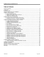
Table of Contents 


Table of Contents ...................................................................................................................... 2


Introduction................................................................................................................................ 3


Symbols in Text ......................................................................................................................... 4


Important Safety Notes For Installation ..................................................................................... 4


Chapter 1 Site Preparation ........................................................................................................ 6


Check Facility Provisions ................................................................................................ 6


Cabinet with Full Rear and Front Doors.......................................................................... 7


Cabinet with Split Rear Door........................................................................................... 8


Chapter 2 Receiving and Unpacking ......................................................................................... 9


Unpacking Instructions- Standard Packaging ............................................................... 10


Unpacking Instructions- Integration Packaging ............................................................. 12


Chapter 3 Configure Accessories into the Cabinet .................................................................. 14


Configure Optional Accessories.................................................................................... 14


Installing and Removing Doors ..................................................................................... 15


Installing and Removing Doors (cont.) .......................................................................... 16


Door Handles ................................................................................................................ 17


How to Reverse the Door Swing ................................................................................... 18


How to Reverse the Door Swing (cont.)........................................................................ 20


Adjusting the Leveling Feet........................................................................................... 21


Installing the Retractable Tip Guard.............................................................................. 22


Installing the Floor Mounting Brackets .......................................................................... 23


Adjusting or Replacing the Mounting Rails ................................................................... 24


How to Remove or Install a Top Panel.......................................................................... 25


How to Remove or Install Side Panels.......................................................................... 26


Installing a Grounding Kit.............................................................................................. 27


Using the SharkTRAC™ and SharkSNAP™ ................................................................ 28


Installing a Typical 19 inch EIA Power Strip (cont.)....................................................... 29


Installing a Typical 19 inch EIA Power Strip (cont.)....................................................... 30


Installing a Typical 19 inch EIA Power Strip (cont.)....................................................... 31


Cable Management....................................................................................................... 32


Installing a MultiBay Kit................................................................................................. 33


Chapter 4 Install Computer Equipment.................................................................................... 34


Cabinet settings for various manufacturers’ devices..................................................... 34


Chapter 5 Final Assembly........................................................................................................ 36


Appendix A: Glossary .............................................................................................................. 37


Appendix B: Basic Cabinet Components ................................................................................. 40


Appendix C: Cabinet Specifications......................................................................................... 42


Warranty .................................................................................................................................. 46


Summary of Contents for 37U

Page 1: ...42 DP 42U Cabinet 37 DP 42 DP 45U Cabinet 37 DP 42 DP ID 00210 000 REV D ECO2773 Page 1 of 46 Proprietary Information of SharkRack Inc 32920 Alvarado Niles Rd Suite 250 Union City CA 94587 510 477 790...

Page 2: ...17 How to Reverse the Door Swing 18 How to Reverse the Door Swing cont 20 Adjusting the Leveling Feet 21 Installing the Retractable Tip Guard 22 Installing the Floor Mounting Brackets 23 Adjusting or...

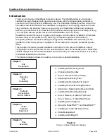
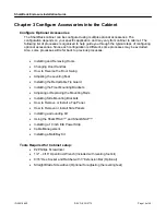
Page 3: ...ove heavy pieces of equipment All the instructions here are presented in great detail This document contains general installation instructions for the various SharkRack cabinet configurations and many...

Page 4: ...cidental or consequential damages in connection with the furnishing performance or use of this material SharkRack assumes no responsibility for the use or reliability of the software or hardware insta...

Page 5: ...moving components from the top portion of the rack improves cabinet stability during relocation Follow these general guidelines whenever you relocate a populated cabinet within a room or building Redu...

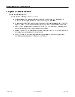
Page 6: ...complete site electrical power supply set up Ensure the types of outlets are consistent with the type of plugs on the power devices to be used Check with a qualified HVAC technician to make sure the...

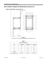
Page 7: ...g Locations for Cabinet with Full Rear and Front Doors Figure 3 42U X 37DP TOP VIEW and 42U X 42DP BOTTOM VIEW Shown Table 1 Cabinet Dimensions DIM 37 CABINET 42 CABINET 45 CABINET A 86 91 82 B 41 46...

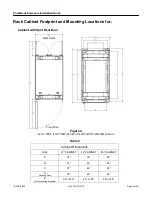
Page 8: ...unting Locations for Cabinet with Split Rear Door Figure 4 42U X 37DP TOP VIEW and 42U X 42DP BOTTOM VIEW Shown Table 2 Cabinet Dimensions DIM 37 CABINET 42 CABINET 45 CABINET A 74 79 82 B 41 46 49 C...

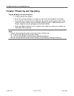
Page 9: ...t of the pallet it requires at least 7 feet for standard packaging with or without pallet and 13 feet for integration crate packaging to unload the cabinet Many SharkRack cabinets come on casters whic...

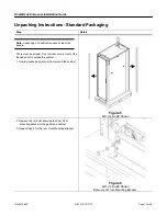
Page 10: ...ople There must be at least 7 feet of clear area in front of the loaded pallet to unload the cabinet 1 Unwrap packaging material from around the cabinet Figure 5 42U X 42in DP Shown 2 Remove the 4 bol...

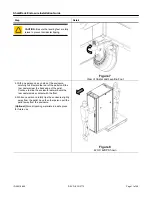
Page 11: ...f the enclosure carefully roll it toward the rear of the pallet until the rear casters clear the back edge of the pallet Continue to slide the enclosure rearward until the rear casters make contact wi...

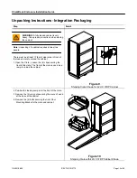
Page 12: ...ar area in front of the loaded crate to unload the cabinet 1 Open the Crate Loosen the 6 clips securing the front of the crate The front of the crate is used as a ramp to unload the cabinet Figure 9 S...

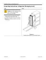
Page 13: ...re the leveling feet are fully raised to prevent accidental tipping See Figure 7 for details 5 With one person on each side of the enclosure carefully roll it out of the wooden crate 6 Unwrap packing...

Page 14: ...efer back to previous processes Installing and Removing Doors Changing Door Handles How to Reverse the Door Swing Adjusting the Leveling Feet Installing the Retractable Tip Guard Installing the Floor...

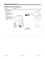
Page 15: ...Installing and Removing Doors Step Detail To remove doors 1 Open the door 2 Pull down on the spring loaded hinge pin attached to the top of the door 3 Move top of door away from enclosure and lift the...

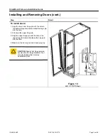
Page 16: ...bottom hinge bracket and slide the hinge pin into the hole 2 Pull down the upper hinge pin 3 Align the upper hinge pin with the hole in the upper hinge bracket and release the hinge pin into the hole...

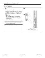
Page 17: ...ks can be networked together for remote management and access tracking To install follow the steps 1 Open the door 2 Rotate the handle to align the cam pointing down 3 Use a screwdriver to push the sn...

Page 18: ...or handle 1 Open the door 2 Rotate the handle to align the cam pointing down 3 Use a screwdriver to push the snaps inward Lift the handle off the door 4 Remove the cam screw securing the cam and rotat...

Page 19: ...773 Page 19 of 46 Step Detail Reverse the door hinge brackets 4 Remove the door See Installing and Removing Doors on page 15 5 Use a Phillips head screwdriver to remove the hinge pin brackets and latc...

Page 20: ...erse the Door Swing cont Step Detail 6 Reinstall the hinge pin brackets and latch bracket s on the opposite side of the cabinet 7 Reinstall the door CAUTION Ensure that the door and its hinge pins are...

Page 21: ...be done before you install products into the cabinet 1 Locate the 4 leveling feet There is one in each corner as shown 2 Loosen the Jam Nut Figure 18 42U X 37DP Shown 3 Lower the leveling feet Rotate...

Page 22: ...the base of the cabinet Detent the spring latches towards the rear of each leg Figure 20 42U X 37DP Shown 2 Check the operation of the Retractable Tip Guard It should freely cycle through its full ra...

Page 23: ...to keep it in a fixed location Consult a contractor or trained professional on the best method of fastening your cabinet to the floor 1 Prepare the location Check the location to make sure the area is...

Page 24: ...unting rail to the desired location Make sure each mounting rail is adjusted parallel and square inside the cabinet 3 Tighten the screws 4 Repeat steps for any other rail to be adjusted Replacing the...

Page 25: ...ft up until you can grab the top panel with your free hand Note If using a grounding kit remove the cable prior to lifting the panel from the Cabinet Frame See Installing a Grounding Kit for details 3...

Page 26: ...other at the same time and tilt the panel outward Note If using a grounding kit remove the cable prior to lifting the panel from the Cabinet Frame See Installing a Grounding Kit for details 3 Release...

Page 27: ...to route the grounding cables through the frame of the cabinet Connection 1 attaches to either of the door assemblies Connection 2 attaches to the side panel Detail B Shows where connection 2 attache...

Page 28: ...ch directly to the SharkTRAC SharkSNAP devices reduce time and hassle when installing things such as power strips patch panels routers and environmental monitoring products Figure 28 1 To install a Sh...

Page 29: ...ll them into the appropriate holes as shown Or Install 10 32 clip nuts as shown Some mounting rails require the use of clip nuts install them into the appropriate holes as shown Figure 30 1b As requir...

Page 30: ...llows a power strip to clip in between them 2a Install a pair of SharkSNAP brackets into the SharkTRAC See Using the SharkTRAC and SharkSNAP on page 28 for further details 2b Approach the SharkSNAP br...

Page 31: ...s the use of cage nuts install them into the appropriate holes using the method shown Figure 34 Cage Nut instillation 3b As required Adjust the mounting brackets orientation Remove the hardware from t...

Page 32: ...signed with integrated cable management There are numerous provisions for running cables in the corner posts of the frame as well as out the top bottom in both the front and back of the cabinet There...

Page 33: ...r equipment into the rack cabinet or after equipment is already loaded Optional Remove the two side panels facing each other from the two cabinets being bayed together See How to Remove or Install Sid...

Page 34: ...e holed L style mounting rails Distance between the front and rear mounting rails needs to be 29 12 inches Many rack mount kits from Compaq use fixed depth side rails and require the cabinet mounting...

Page 35: ...ired use a fully vented front door If a front door is required you may need to set all mounting rails back Sun Sun has not published a corporate wide set of racking requirements for 3rd party cabinets...

Page 36: ...s for your specified power requirements Check that there is no obstruction to any device that needs to be accessed for maintenance Check that there is easy access to the power strips Check that all fa...

Page 37: ...omponents parts systems and equipment for communications industrial government and consumer uses U or RU A Rack Unit or sometimes referred to as U is the measure of space in a rack cabinet enclosure e...

Page 38: ...gure 40 Cage Nut Clip Nut A fastener typically used on round hole universal type racks similar to a Cage Nut They come in different shapes and sizes You must specify the thread type as well as the thi...

Page 39: ...000 REV D ECO2773 Page 39 of 46 Appendix A Glossary cont SharkTRAC The SharkTRAC is a platform consisting of a series of holes which allows attachment of various devices such as the family of SharkSNA...

Page 40: ...Cabinet Components Note Before you begin configuring your SharkRack cabinet it is best to verify that you have received all necessary items to begin your installation Also verify that your equipment h...

Page 41: ...t Bracket Latch Full Rear Door 1 Snap In swing Handle 1 Grommet Bumper 2 Rear Hinge Bracket Top Left Bottom Right 1 Rear Hinge Bracket Top Right Bottom Left 1 10 32X 375 Flat Head Screw 8 Full Rear Do...

Page 42: ...art in Table 2 is taken from SharkRack s latest generation of racks Previous generations vary from that listed bellow Note The Reference column of Table 2 references the Figures and the following page...

Page 43: ...SharkRack Enclosure Installation Guide ID 00210 000 REV D ECO2773 Page 43 of 46 Cabinet Dimensions Top View Figure 45 Cabinet Dimensions...

Page 44: ...SharkRack Enclosure Installation Guide ID 00210 000 REV D ECO2773 Page 44 of 46 Mounting Rail Dimensions Front View Figure 46 Mounting Rails...

Page 45: ...3 16 Figure 14 17 Figure 15 18 Figure 16 19 Figure 17 20 Figure 18 21 Figure 19 21 Figure 20 22 Figure 21 22 Figure 22 23 Figure 23 23 Figure 24 24 Figure 25 25 Figure 26 26 Figure 27 27 Figure 28 28...

Page 46: ...IMS ANY AND ALL OTHER WARRANTIES WHETHER EXPRESS IMPLIED OR STATUTORY INCLUDING WITHOUT LIMITATION ANY IMPLIED WARRANTIES OF MERCHANTABILITY FITNESS FOR A PARTICULAR PURPOSE QUALITY OR NONINFRINGEMENT...

Reviews: