


WPC
7
5.2 Connecting Mainboard and Graphics Card(s)
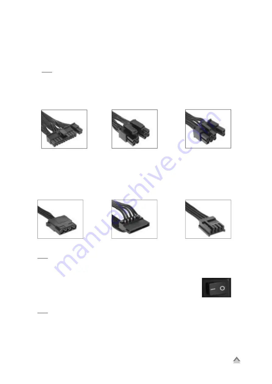
1. Plug the 20+4-pin mainboard connector (Fig. 1) into the respective port of the mainboard.
2. If your mainboard also features either a 4-pin or 4+4-pin CPU connector, connect the plug with the
mainboard port (Fig. 2).
Note:
The power connection of the mainboard depends on the vendor and may vary. For detailed information on
how to establish the power connector, please refer to your mainboard’s manual.
3. If your PCIe graphics card requires an additional power supply, connected the 6-pin or 6+2-pin PCIe con-
nector to ensure the graphics card receives a stable power supply (Fig. 3).
5.3 Connecting Optical Drives and Other Peripheral Devices
Connect the IDE connector (Fig. 4), SATA connector (Fig. 5) and the Floppy connector (Fig. 6) with the appro-
priate peripherals.
Note:
For additional information, refer to the respective manuals of your drives and peripheral devices.
5.4 Checking All Connections
Ensure that all devices are properly connected. Close the PC case. Connect the power
cord with the power supply and wall outlet. Turn the power supply on. This completes
the installation of the power supply.
Note:
All connectors are designed to avoid misconnection. If the connectors are unable to connect to the main-
board, drives or peripheral devices, please check if both connectors are attached in the correct orientation.
Do not force to plug the connectors within the incorrect orientation, nor modify any of the components, as
this will damage the power supply and other hardware. SHARKOON warranty does not cover damage cause
by incorrect handling.
Fig. 1: 20+4-Pin Mainboard Connector
Fig. 2: 4+4-Pin CPU Connector
Fig. 3: 6+2-Pin PCIe Connector
Fig. 4: IDE Connector
Fig. 5: SATA Connector
Fig. 6: Floppy Connector
On/Off Switch for
the Power Supply
Summary of Contents for WPC Bronze Series
Page 1: ...Manual...


