background image

scorpio 1000/2000

7.  Installing an optical device

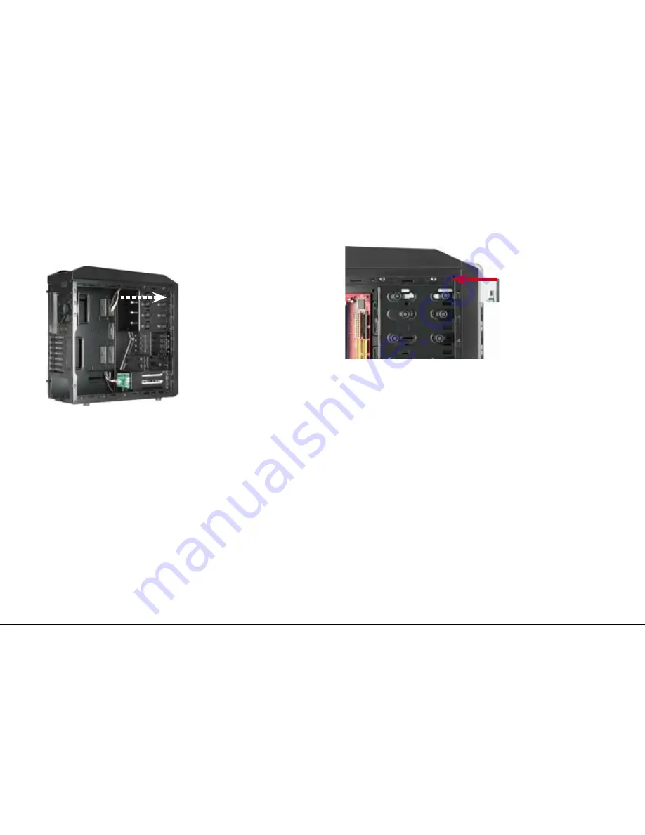
1.   Reach into the case and push out the 5.25" front bezel from the  
 

mounting bay where you want to install the drive (fig. 17).


fig. 17


2.   Insert the optical drive into the case’s drive bay and attach it from  
 

both sides using the pre-installed quick fasteners (fig. 18).


fig. 18

3.   Connect the optical drive to the power supply and the mainboard.


Note:


If  you  intend  to  transport  the  case  we  recommend  securing  


(additionally) the installed drives.

Summary of Contents for SCORPIO 1000

Page 1: ...Manual...

Page 2: ...7 Installing an optical device 8 Installing an add on card 9 The pre installed fans 10 Installing additional fans optimized airflow 10 1 Side panel 10 2 Top panel Dear customer Congratulations for pur...

Page 3: ...n opening for CPU coolers 2 openings for water cooling Cable management system Black interior painting Dimensions 508 x 210 x 503 mm L x W x H Weight 7 25 kg Fan configuration Scorpio 1000 Case front...

Page 4: ...s for mainboard 10x screws for drive mainboard mounting 4x screws for HDD PSU mounting 10x screws with coarse thread for HDD mounting 12x screws with fine thread for HDD mounting 4x fan screws 4x moun...

Page 5: ...front bezel 120 mm LED fan blue pre installed D Fast Swap drive bays incl pre installed 80 mm fan Top view A Ventilation openings B Top I O a On off button b Reset button c 2x USB2 0 connectors d 1x h...

Page 6: ...D Quick fasteners for optical drives E Mounting cage for 2 5 HDDs SSDs F Mounting cage for 3 5 HDDs G Fast Swap drive bays H Cable openings I Circuit board to connect the front fans no fan control a C...

Page 7: ...w A Case feet B Air intake PSU The internal cables and connectors A Connectors for Reset Switch HDD LED Power LED Power LED Power Switch B USB connector of the USB front hub C Audio connectors HD Audi...

Page 8: ...w in the stand offs fig 1 fig 1 The mainboard contains special screw openings fig 2 fig 2 Place the mainboard to the mounting panel A stand off must be screwed into every drilling of the mounting pane...

Page 9: ...A cable connected to the front eSATA connection should not exceed 50 cm of length otherwise transmission errors may occur With premium quality eSATA cables this maximum length may be exceeded 5 Instal...

Page 10: ...board fig 8 fig 8 5 2 3 5 HDD cage 1 Attach the mounting rails to the 3 5 HDD from both sides fig 9 fig 9 4 Screw the HDD to the mounting frame from below fig 7 Screws with coarse thread for HDD mount...

Page 11: ...built in HDD to the mainboard 5 3 3 5 drive bay 1 Remove the case s left and right side panel 2 Insert a 3 5 HDD into the drive bay below the Fast Swap drive bays inside the case fig 11 fig 11 3 Screw...

Page 12: ...t the PSU from the inside against the PSU bracket on the case s back side fig 14 fig 14 Note The PSU may be installed in two different directions either the fan points upwards towards the mainboard or...

Page 13: ...ant to install the drive fig 17 fig 17 2 Insert the optical drive into the case s drive bay and attach it from both sides using the pre installed quick fasteners fig 18 fig 18 3 Connect the optical dr...

Page 14: ...fans 1 The pre installed case fans provide a 3 pin mainboard plug each 2 Connect the plugs to either the respective mainboard or fan connector of the circuit board fig 20 fig 20 10 Installing additio...

Page 15: ...the fan to the respective fan bracket from the inside Screw the fan to the fan bracket from the outside fig 22 fig 22 4 Connect the fan s power connector to the PSU or the mainboard Note While install...

Page 16: ...cations reserved Disposal of your old product Your product is designed and manufactured with high quality materials and components which can be recycled and reused When this crossed out wheeled bin sy...

Reviews: