background image

GB 


Idea Par Led Zoom RGB 


XM368-V1.2 -B


17 

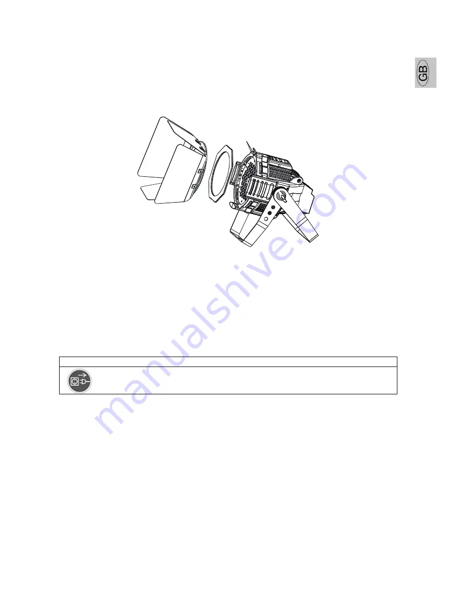
INSTRUCTIONS FOR INSTALLING THE BARN-DOOR AND FROST FILTER 

For this device, the barn door and the frost filter can be installed separately or together. 

1.


When only install the frost filter, use the rotating clips on the lens cover to fix it. 

2.


When only install the bar door, loose the 2 M4 screws on the lens cover, put on the bar door and tighten 
the screws. 

3.


When install the bar door and frost filter together, loose the 2 M4 screws, put on the frost filter and the 
bar door one by one, then tighten the screws. 


Loose the 2 screws


CLEANING AND MAINTENANCE 

The following points have to be considered during the inspection: 

1)


All screws for installing the devices or parts of the device have to be tightly connected and must not be 
corroded. 

2)


There must not be any deformations on the housing, fixations and installation spots (ceiling, 
suspension, trussing). 

3)


Mechanically moved parts must not show any traces of wearing and must not rotate with unbalances. 

4)


The electric power supply cables must not show any damage, material fatigue or sediments.   

Further instructions depending on the installation spot and usage have to be adhered by a skilled installer 
and any safety problems have to be removed. 
 

CAUTION


Disconnect from mains before starting maintenance operation. 

 
In order to make the lights in good condition and extend the life time, we suggest a regular cleaning to the 
lights. 

1)


Clean the inside and outside lens each week to avoid the weakneness of the lights due to accumulation 
of dust. 

2)


Clean the fan each week. 

3)


A detailed electric check by approved electrical engineer each three month, make sure that the circuit 
contacts are in good condition,    prevent the poor contact of circuit from overheating.   

Should you need any spare parts, please order genuine parts from your local dealer. 
 

Summary of Contents for Idea Par LED Zoom RGB

Page 1: ...ONS 3 GENERAL GUIDELINES 4 INSTALLATION INSTRUCTIONS 5 Mounting the device 5 Overhead rigging 6 DMX 512 control connection Errore Il segnalibro non definito Control Board 8 Main functions 9 INSTRUCTIO...

Page 2: ...ser manual from the Internet INTRODUCTION Thank you for having chosen this professional LED lighting You will see you have acquired a powerful and versatile device Unpack the device Inside the box you...

Page 3: ...aler will not accept liability for any resulting defects or problems If the device has been exposed to temperature changes due to environmental changes do not switch it on immediately The arising cond...

Page 4: ...professionals GENERAL GUIDELINES This device is a lighting effect for professional use on stages in discotheques theatres etc This fixture is only allowed to be operated with the max alternating curr...

Page 5: ...ne technical installations are approved by an expert before taking the device into operation for the first time These installations have to be approved by a skilled person once a year CAUTION Before t...

Page 6: ...control connection The product has a DMX 512 input fitted with standard 5 pin XLR connectors Screened cables in compliance with EIA RS 485 specifications and the following characteristics must be use...

Page 7: ...MX starting address when using a DMX signal so that the correct fixture responds to the correct control signals This digital starting address is the channel number from which the fixture starts to lis...

Page 8: ...sensitivity FAIL OFF HOLD AUTO SOUN No DMX Status REST Reset DFSE ON OFF Restore factory settings POHO ON OFF Power on to preserve the MANL settings 1 SET VER V 1 0 V 9 9 Software version 2 MANL RED...

Page 9: ...this function you can define the device as slave 1 Select SLAV by pressing UP or DOWN button 2 Press ENTER the display shows ON or OFF 3 Press UP to select ON if you wish to enable this function or p...

Page 10: ...rm the display shows D 00 In this setting the DMX adjustment of every channel will be displayed 3 Press UP or DOWN button in order to select the desired channel If you select D 12 the display will onl...

Page 11: ...umber from 0 to 99 3 Press ENTER to confirm or Press MENU to return to the main menu Automatic Run by no DMX With this function you can automatic run the device by no DMX 1 Select FAIL by pressing UP...

Page 12: ...Manual adjust intensity 1 Select MANL by pressing UP or DOWN button 2 Press ENTER the display shows RED GREN BLUE MACO PROG STRB DIMM ZOOM 3 Press UP or DOWN button to select RED GREN BLUE MACO PROG...

Page 13: ...ion you can edit the program to be called up in Run a Editing via the Control Board 1 Select SC01 by pressing UP or DOWN button 2 Press ENTER the display shows SCXX X stands for the scene no to be edi...

Page 14: ...ws FADE Adjust fade speed 6 Press ENTER the display to be adjust fade speed 7 Select CEDT by pressing UP or DOWN button 8 Press ENTER the display shows OFF 9 Press UP or DOWN button the display shows...

Page 15: ...macro 6 48 55 Color macro 7 56 63 Color macro 8 64 71 Color macro 9 72 79 Color macro 10 80 87 Color macro 11 88 95 Color macro 12 96 103 Color macro 13 104 111 Color macro 14 112 119 Color macro 15...

Page 16: ...ram 7 5 221 255 Gradient effect Shutter strobe 0 31 Led trun off 32 63 Led turn on 64 95 Strobe effect slow to fast 96 127 Led turn on 128 159 Pulse effect in sequences 160 191 Led turn on 192 223 Ran...

Page 17: ...s on the housing fixations and installation spots ceiling suspension trussing 3 Mechanically moved parts must not show any traces of wearing and must not rotate with unbalances 4 The electric power su...

Page 18: ...sumption max 120 W Packing dimensions 40 x 30 x 48 CM Flight case dimensions 79x76 5x60 cm Net weight 7 KGS Gross weight 10KGS carton packing 75 5 KGS flight case packing 6pcs Remark errors and omissi...

Reviews: