17
Connect/disconnect head and base
Installing ceiling mount bracket
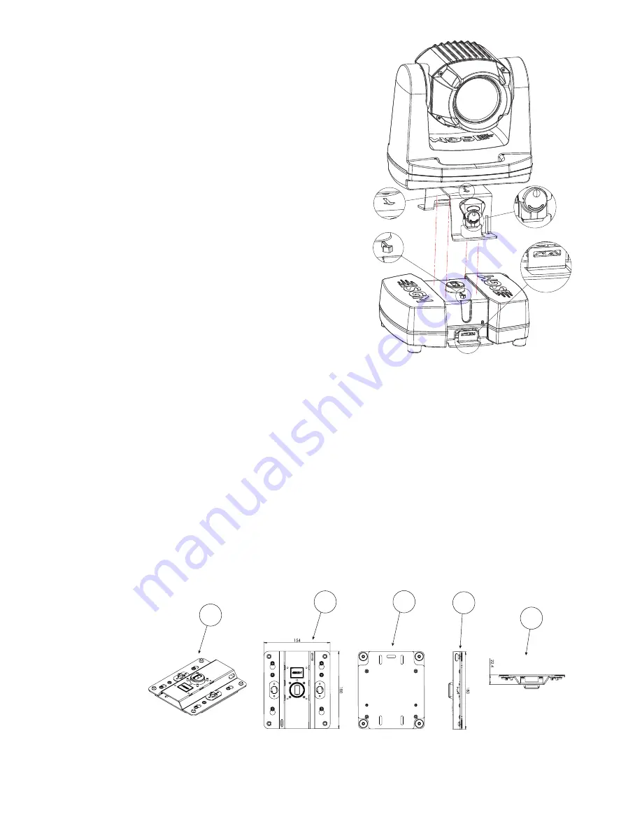
Mounting the head on the base
First of all, ensure that the base of the fixture is not connected to AC power.
While powered off, start over by mounting the base of the fixture. This is easily
done in four steps:
1.
Make sure the arrow on the head bracket (DETAIL A) points towards
the same direction as the arrow on the base (DETAIL B).
2.
Make sure the two butterfly locks (DETAIL C) are in locked position
so that they do not get jammed when mounting the head to the base.
3.
Carefully position the head on the base, making sure that the arrow
on the base unit (DETAIL B) slides into the arrow on the head bracket
(DETAIL A). Additionally, a slot on the head bracket slides over the
guide knob on the base unit to steer the downwards movement.
4.
After the head has been properly positioned on the base, use the
butterfly locks (DETAIL C) to fasten the head securely to the base
(DETAIL D).
Removing the head from the base
After ensuring the fixture is not connected to AC power, start removing the
head from the base following the steps below:
1.
Loosen the two butterfly locks on the head bracket (DETAIL C) from
the base (DETAIL D).
2.
With a firm grip, gently pull the head away from the base in a straight
upwards movement.
CAUTION:
Be careful when connecting/disconnecting the head from the base in order to avoid damaging the connectors between
the head and the base.
Please note: the head is not detachable on the POI version.
The ceiling mount bracket lets the fixture replace the base unit and to be mounted directly to a surface. Also, it supports the ability to
be hung with 1/4-turn omega bracket.
The ceiling mount is fitted directly to the head and offers a very low installation height.
When using ceiling mount there are two options for powering the fixture:
1.
Power from an external 24V power supply.
2.
Use an SGM extension cable, that connects the base to the ceiling mount.
Contact your SGM dealer, or [email protected], for more information about the extension cable.
Overview
DETAIL C
DETAIL A
DETAIL D
DETAIL B
Figure 17: Ceiling mount bracket
A: ISO View
B: Front view
C: Back view
D: Right side view
E: Top view
A
E
B
D
Measurements in millimeters
C
Figure 16: Removing G-1 Beam head
Summary of Contents for G-1 BEAM
Page 1: ...USER MANUAL MOVING HEADS SERIES G 1 BEAM G 1 BEAM POI ...
Page 30: ...30 User Notes ...
Page 31: ...31 User Notes ...


