background image

-4-


● Meet EN 61010-1 CAT III 600V

EN 61326

EN 61000-4-2

EN 61000-4-3


● BS 16

th

 edition

5. Measuring Methods

OPERATION CAUTION 


Observe all safety precautions when the FUNCTION 

switch is set to 250,500V,1000V position.  Connect 

the meter test leads to the circuit under test before 

operating the TEST button. Do not touch the clip ends 

of  the  test  leads when the TEST button is pressed. 

Some electrical equipment, especially cables, may 

retain an electrical charge when disconnected 

from the line.  It is good practice to discharge such 

equipment with grounding straps, or other suitable 

devices, before touching or making connections.  The 

meter automatically discharge the test circuits when 

the spring loaded TEST button is released.


IMPORTANT  


Remove all power to the circuit under test when 

making resistance measurements.  If any voltage is 

present in the test circuit the LED on the meter scale 

plate will light.  Immediately disconnect the test leads 

and turn off power to test circuit. 

Summary of Contents for 2751 IN

Page 1: ...INSTRUCTION MANUAL 2751 IN INSULATION TESTER...

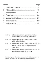
Page 2: ...of the low voltage installation CAT III Is for measurements performed in the building Installation CAT II Is for measurements performed on circuits directly connected to the low voltage installation C...

Page 3: ...1 1 Instrument Layout FUNCTION SWITCH EXTERNAL VOLTAGE INDICATOR OUTPUT TERMINAL LCD DISPLAY POWER INDICATOR DATA HOLD BUTTON TEST BUTTON NULL ADJUST...

Page 4: ...AD SAFETY NOTES NEXT PAGE BEFORE USING THE METER 3 Safety Notes Read the following safety information carefully before attempting to operate or service the meter Use the meter only as specified in thi...

Page 5: ...Features 3 Digit Insulation Tester 68mm x 34mm 1 338 x 2 677 large LCD display Three insulation test voltage 250V 500V 1000VDC The output voltage is 1000VDC External voltage warning indication Automa...

Page 6: ...ctrical equipment especially cables may retain an electrical charge when disconnected from the line It is good practice to discharge such equipment with grounding straps or other suitable devices befo...

Page 7: ...the leads are faulty or instrument fuse is blown See Fuse Replacement section Insulation Resistance Testing Warning Insulation tests should be conducted on circuits that are de energised Ensure circui...

Page 8: ...ument Never touch the circuit during insulation testing When testing is complete ensure the TEST button is released before the test leads are disconnected This is because the system may be charged up...

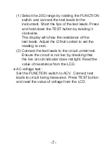
Page 9: ...he resistance of the test leads Adjust the Null control to set the reading to zero 2 Connect the test leads to the circuit under test Ensure the circuit is not live by checking that the live circuit i...

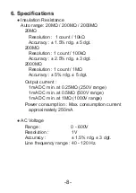
Page 10: ...nt 100k Accuracy 2 5 rdg 3 dgt 2000M Resolution 1 count 1M Accuracy 5 rdg 5 dgt Output current 1mA DC min at 0 25M 250V range 1mA DC min at 0 5M 500V range 1mA DC min at 1M 1000V range Power consumpti...

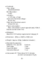
Page 11: ...n Max consumption current approximately 160mA Buzzer sounds under 10 Withstand Meet IEC 1010 safety requirements Category III Dimension 205 L x 90 W x 55 D mm Weight Approx 600g batteries included Sta...

Page 12: ...batteries are recommended Replace the battery compartment lid Fuse Replacement Open the battery compartment lid Remove the fuse cove and the old fuse and replace with the new one Replace the fuse cov...

Reviews: