Gear Units for Trolley Drive Systems - Operating Instructions
7
3
Installing the gear unit
Use plastic inserts (2–3 mm thick) if there is a risk of electrochemical corrosion between
the gear unit and the driven machine (connection between different metals such as cast
iron and high-grade steel)! Also fit the bolts with plastic washers! Ground the housing
additionally – use the grounding bolts on the motor.
Installation in
damp areas or on
the outside
Gear units are supplied in corrosion-resistant versions for use in damp areas or in the
open air. Any damage to the paintwork (e.g. on the breather valve) must be repaired.
Gear unit
venting
All gear units are delivered by SEW ready for the mounting position with the breather
valve and transport fixture fitted.
Exception:
Gear units for extended storage, pivoting and inclined mounting positions are delivered
with a screw plug on the intended vent hole. Prior to startup, the customer must replace
the highest screw plug by the supplied breather valve on each individual gear unit!
•
With geared motors (for extended storage, pivoting or inclined mounting position),
the supplied breather valve is located in the terminal box on the motor.
•
With mount-on units that must breathe on the input side, a breather valve is
supplied in a plastic bag.
•
With gear units in an enclosed design no breather valve is supplied.
Activating the
breather valve
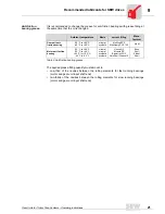
Usually the breather valve is activated ex-works. Should this not be the case, the
transport fixture must be removed from the breather valve prior to the startup of
the gear unit!
Painting the gear
unit
If the drive is to be overpainted or partially repainted, ensure that the breather valve and
the oil seals are carefully covered with tape. Remove the tape strips after the paint work
is finished.
1. Breather valve with
transport fixture
2. Remove the transport fixture
3. Breather valve activated
02053BXX
02054BXX
02055BXX
Summary of Contents for HK40
Page 2: ...SEW EURODRIVE ...


