background image

Operating Instructions Gear Units for Trolley Drive Systems

3

1 Important 

Notes................................................................................................. 4

2 Safety 

Instructions............................................................................................ 5

3 Installation ......................................................................................................... 6

3.1

Before you begin....................................................................................... 6

3.2

Preliminary work ....................................................................................... 6

3.3

Installing the gear unit............................................................................... 6

4 Assembly 

Disassembly .................................................................................. 8

4.1

Required tools........................................................................................... 8

4.2

Installing the drive rod............................................................................... 8

4.3

Gear units with solid shafts ....................................................................... 8

5 Commissioning ............................................................................................... 10

5.1

Commissioning of gear units


HW30 and helical-worm gear units HS..... 10

6 Inspection 

Maintenance ............................................................................... 11

6.1

Inspection and maintenance intervals..................................................... 11

6.2

Lubricant change intervals ...................................................................... 11

6.3

Inspection and maintenance ................................................................... 12

Operation and Service .................................................................................... 13
7.1

Gear unit malfunction.............................................................................. 13

8 Mounting 

Positions......................................................................................... 14

8.1

General information on mounting positions ............................................ 14

8.2

HW30 D.. ................................................................................................ 15

8.3

HS40 D.., HS41 D................................................................................... 16

8.4

HK40D... ................................................................................................. 17

8.5

HS50 D.., HS60 D................................................................................... 18

9 Technical 

Data................................................................................................. 19

9.1

Lubricant filling quantities........................................................................ 19

9.2

Recommended lubricants for SEW drives .............................................. 20

0

0

I

P

i

f

kVA

Hz

n

Summary of Contents for HK40

Page 1: ...Geared Motors HW30 HS40 HS41 HK40 HS50 HS60 for Trolley Drive Systems Edition 07 2000 Operating Instructions 1050 4214 EN ...

Page 2: ...SEW EURODRIVE ...

Page 3: ... 5 1 Commissioning of gear units HW30 and helical worm gear units HS 10 6 Inspection Maintenance 11 6 1 Inspection and maintenance intervals 11 6 2 Lubricant change intervals 11 6 3 Inspection and maintenance 12 7 Operation and Service 13 7 1 Gear unit malfunction 13 8 Mounting Positions 14 8 1 General information on mounting positions 14 8 2 HW30 D 15 8 3 HS40 D HS41 D 16 8 4 HK40D 17 8 5 HS50 D ...

Page 4: ...components gears shafts and rolling bearings of gear units should be disposed of as steel scrap The same applies to components made of cast iron if no separate collection is available Helical worm wheels consist partially of non ferrous metal and should be disposed of accordingly Collect used oil and dispose of it according to applicable regulations In case of design changes adjust the lubricant f...

Page 5: ...e housing Intended usage These geared motors gear units are intended for industrial systems They comply with existing standards and regulations The technical data and information on approved conditions can be found on the nameplate and in the documentation All these details must be observed Transport Storage Inspect shipment for possible transport damages upon receipt Immediately inform the shippi...

Page 6: ...he bearings is reduced if the unit is stored 1 year Gear unit designs of the extended storage type have an oil fill suitable for the mounting position so the unit is ready to run mineral oil Nevertheless check the oil level prior to startup see Lubricant filling quantities on page 19 a partially higher oil level if synthetic oil is used Correct the oil level prior to startup see Lubricant filling ...

Page 7: ...ered with a screw plug on the intended vent hole Prior to startup the customer must replace the highest screw plug by the supplied breather valve on each individual gear unit With geared motors for extended storage pivoting or inclined mounting position the supplied breather valve is located in the terminal box on the motor With mount on units that must breathe on the input side a breather valve i...

Page 8: ...d shafts Mounting of carrying wheels Figure 1 shows an example of a mounting device for the installation of a carrying wheel onto the gear unit or motor shaft ends It may be possible to dispense with the thrust bearing on the mounting device 03605AXX Figure 1 Example of a mounting device for installation of carrying wheels Shaft end Flanges Diametric tolerances in accordance with DIN 748 ISO k6 fo...

Page 9: ... to bearings housing and the shaft Power transmission elements should be balanced after fitting and must not give rise to any impermissible radial or axial forces see Figure 2 permitted values see the Trolley drive systems catalog Note Assembly is easier if you first apply lubricant to the output element or heat it up briefly 80 to 100 C Input and output elements such as carrying wheels must have ...

Page 10: ...HS require a running in period of at least 24 hours before reaching their maximm efficiency A separate running in period for each direction of rotation is required if the gear unit is operated in both directions of rotation Table 1 shows the average power reduction during the running in period Table 1 Power reduction for helical worm gear units HS and Spiroplan gear units HW30 Power reduction for ...

Page 11: ...ive environmental conditions Interval What to do Section Every 3000 machine hours At least every six months Check the oil see Section 6 3 Depending on operating conditions Figure 3 at least every 3 years Change mineral oil Renew the anti friction bearing Depending on operating conditions Figure 3 at least every 5 years Change synthetic oil Renew the anti friction bearing Spiroplan gear units HW30 ...

Page 12: ...istency viscosity if the oil is visibly strongly contaminated it is recommended to change it sooner than specified in the maintenance intervals in section 6 1 4 For gear units with oil level plug Remove oil level plug check oil level and adjust if necessary replace oil level plug Changing the oil Change the oil only when the gear unit is at operating temperature 1 Disconnect the drive and secure i...

Page 13: ...the oil Section 6 3 2 Stop the drive contact customer service Oil leaking 1 from the motor flange from the motor oil seal from the gear unit flange from the output end oil seal 1 It is normal for small amounts of oil grease to leak out of the oil seal during the running in phase 24 hour running time a Seal defective b Gear unit not vented for a Call customer service for b Vent the gear unit Sectio...

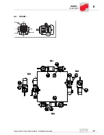
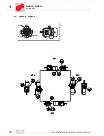
Page 14: ...ions M1 M4 with right angle geared motors for trolley drive systems The following figure shows the spatial position of the gear unit with mounting positions M1 M4 03564AXX Figure 9 Representation of mounting positions M1 M4 for right angle geared motors List of symbols The following table shows the symbols used in the mounting position sheets and their meanings M1 M4 M3 M2 Symbol Meaning Breather ...

Page 15: ...Gear Units for Trolley Drive Systems Operating Instructions 15 8 HW30 D 8 2 HW30 D M1 M4 M2 M3 270 90 180 0 Normal Normal Normal 1 3 2 Normal 06 007 000 ...

Page 16: ...8 16 Gear Units for Trolley Drive Systems Operating Instructions HS40 D HS41 D 8 3 HS40 D HS41 D M1 M4 M3 M2 270 90 180 0 Normal Normal Normal 1 3 2 Normal 06 008 000 ...

Page 17: ...Gear Units for Trolley Drive Systems Operating Instructions 17 8 HK40D 8 4 HK40D M1 M2 M4 M3 270 90 180 0 Normal Normal Normal 1 3 2 Normal 06 009 000 ...

Page 18: ...8 18 Gear Units for Trolley Drive Systems Operating Instructions HS50 D HS60 D 8 5 HS50 D HS60 D M1 M4 M3 M2 270 90 180 0 Normal Normal Normal 1 3 2 Normal 06 010 000 ...

Page 19: ...ng quantities with respect to the mounting positions M1 M4 It is essential to use the oil level screw as an indicator of the correct lubricant quantity during filling Table 3 Lubricant filling quantities Gear unit type Filling quantity in liter M1 M2 M3 M4 HW30 0 65 0 65 0 65 0 75 HS40 1 2 1 45 0 95 1 9 HS41 1 2 1 45 0 95 1 9 HK40 2 0 2 0 2 3 2 8 HS50 1 4 1 4 1 5 2 2 HS60 2 8 2 7 2 8 4 1 ...

Page 20: ... VG 460 Mobil SHC 634 Shell Omala 460 HD Klübersynth GEM 4 460 40 10 CLP PG VG 150 Mobil SHC 629 Klübersynth GEM 4 150 20 10 CLP CC VG 150 VG 100 Mobil D T E 18M Shell Omala 100 Klüberoil GEM 1 150 Aral Degol BG 100 BP Energol GR XP 100 Tribol 1100 100 Meropa 100 Optigear BM 100 Renolin CLP 150 25 20 CLP PG VG 220 1 Mobil Glygoyle 30 Klübersynth GH 6 220 Tribol 800 220 Synlube CLP 220 Optiflex A 2...

Page 21: ...etween the rolling elements for fast running bearings motor and gear unit input shaft end two thirds of the cavities between the rolling elements for slow running bearings motor and gear unit input shaft end Ambient temperature Basis current filling Manu facturer Gear unit anti friction bearing 30 C to 60 C 40 C to 80 C mineral synthetic Mobilux EP 2 Mobiltemp SHC 100 Mobil Motor anti friction bea...

Page 22: ... 0 21 73 85 07 30 Fax 0 21 73 85 07 55 G e r m a n y 0 6 Meerane near Zwickau SEW EURODRIVE GmbH Co Dänkritzer Weg 1 D 08393 Meerane Phone 0 37 64 76 06 0 Fax 0 37 64 76 06 30 G e r m a n y 0 7 Additional addresses for service in Germany provided on request France F r a n c e 0 1 Production Sales Service Haguenau SEW USOCOME SAS 48 54 route de Soufflenheim B P 185 F 67506 Haguenau Cedex Phone 03 8...

Page 23: ...ulo SEW DO BRASIL Motores Redutores Ltda Caixa Postal 201 0711 970 Rodovia Presidente Dutra km 213 CEP 07210 000 Guarulhos SP Phone 011 64 60 64 33 Fax 011 64 80 43 43 sew brasil originet com br Bulgaria B u l g a r i a 0 1 Sales Sofia BEVER DRIVE GMBH Bogdanovetz Str 1 BG 1606 Sofia Phone 92 9 53 25 65 Fax 92 9 54 93 45 bever mbox infoPhone bg Canada C a n a d a 0 1 Assembly Sales Service Toronto...

Page 24: ...G r e e c e 0 1 Sales Service Athens Christ Boznos Son S A 12 Mavromichali Street P O Box 80136 GR 18545 Piraeus Phone 14 22 51 34 6 14 22 51 48 9 Fax 1 4 22 51 59 Boznos otenet gr Great Britain G r e a t B r i t a i n 0 1 Assembly Sales Service Normanton SEW EURODRIVE Ltd Beckbridge Industrial Estate P O Box No 1 GB Normanton West Yorkshire WF6 1QR Phone 19 24 89 38 55 Fax 19 24 89 37 02 Hungary ...

Page 25: ...IVE Sdn Bhd 95 Jalan Seroja 39 81100 Johore Bahru Johore Phone 07 3 54 57 07 3 54 94 09 Fax 07 3 5414 04 Netherlands N e t h e r l a n d s 0 1 Assembly Sales Service Rotterdam VECTOR Aandrijftechniek B V Industrieweg 175 NL 3044 AS Rotterdam Postbus 10085 NL 3004AB Rotterdam Phone 010 4 46 37 00 Fax 010 4 15 55 52 New Zealand N e w Z e a l a n d 0 1 Assembly Sales Service Auckland SEW EURODRIVE NE...

Page 26: ...9 42 300 S o u t h A f r i c a 0 2 Capetown SEW EURODRIVE PROPRIETARY LIMITED Rainbow Park Cnr Racecourse Omuramba Road Montague Gardens 7441 Cape Town P O Box 53 573 Racecourse Park 7441 Cape Town Phone 021 5 11 09 87 Fax 021 5 11 44 58 Telex 576 062 S o u t h A f r i c a 0 3 Durban SEW EURODRIVE PROPRIETARY LIMITED 39 Circuit Road Westmead Pinetown P O Box 10433 Ashwood 3605 Phone 031 700 34 51 ...

Page 27: ...o SEW EURODRIVE INC 30599 San Antonio Road P O Box 3910 Hayward California 94544 Phone 510 4 87 35 60 Fax 510 4 87 63 81 U S A 0 3 Philadelphia PA SEW EURODRIVE INC Pureland Ind Complex 200 High Hill Road P O Box 481 Bridgeport New Jersey 08014 Phone 856 4 67 22 77 Fax 856 8 45 31 79 U S A 0 4 Dayton SEW EURODRIVE INC 2001 West Main Street Troy Ohio 45373 Phone 9 37 3 35 00 36 Fax 9 37 4 40 37 99 ...

Page 28: ...SEW EURODRIVE GmbH Co P O Box 30 23 D 76642 Bruchsal Germany Tel 49 72 51 75 0 Fax 49 72 51 75 19 70 http www SEW EURODRIVE com sew sew eurodrive com ...

Reviews: