3
6
Gear Units for Trolley Drive Systems - Operating Instructions
Before you begin
3
Installation
3.1
Before you begin
The drive may
only be installed
if
•
the entries on the nameplate of the geared motor match the supply voltage
•
the drive is not damaged (no damage resulting from transport or storage)
•
it is certain that the following requirements have been fulfilled:
– with all gear units:
ambient temperature between 0 °C and +40 °C, no
oils, acids, gases, vapors, radiation, etc.
– with special versions:
drive configured according to ambient conditions
– with Spiroplan
®
gear unit HW30 and helical-worm gear HS..:
no large external mass moments of inertia are present that could exert a restoring
load on the gear unit (with
η
’ (restoring) = 2 – 1/
η
< 0.5 self-locking)
3.2
Preliminary work
Output shafts and flange surfaces must be thoroughly cleaned of anti-corrosion agents,
contamination or similar impurities (use a commercially available solvent). Do not let the
solvent get in contact with the sealing lips of the oil seals – danger of damage to the
material!
Please note: The service life of the lubricant in the bearings is reduced if the unit is
stored
≥
1 year.
Gear unit designs of the "extended storage" type have
•
an oil fill suitable for the mounting position so the unit is ready to run (mineral oil).
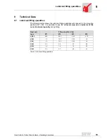
Nevertheless, check the oil level prior to startup (see “Lubricant filling quantities" on
page 19).
•
a partially higher oil level if synthetic oil is used. Correct the oil level prior to startup
(see “Lubricant filling quantities" on page 19).
3.3
Installing the gear unit
The gear unit or geared motor must be mounted/installed in the specified mounting
position (Spiroplan
®
gear units are not dependent upon mounting position) on a level
1)
,
vibration-absorbing and torsionally rigid support structure. Do not tighten housing legs
and mounting flanges against each other.
At this point of assembly, please check that the oil filling is as specified for the mounting
position.
In case of design changes, adjust the lubricant filling amounts accordingly.
Where the mounting position of HS gear units is to be changed to mounting position M2,
please consult the SEW service department.
1) Maximum permitted flatness error for flange mounting (approximate value with reference
to DIN ISO 1101): with
→
flange 120 – 600 mm max. error 0.2 – 0.5 mm
The oil check and drain screws and the breather valves must be freely accessible!
Summary of Contents for HK40
Page 2: ...SEW EURODRIVE ...


