5
10.
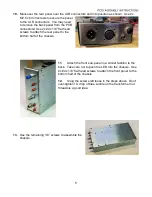
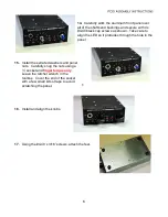
Maneuver the rear panel over the XLR connectors and into position as shown. Use 2x
M2.5 x 6mm screws to secure the panel
to the XLR connectors. You may need
to remove the back panel from the PCB
connectors!
Use 2x #4 x 1/8” flat head
screws to attach the rear panel to the
bottom half of the chassis.
11.
Attach the front sub-panel in a similar fashion to the
back. Take care not to push the LED into the chassis. Use
2x #4 x 1/8” flat head screws to attach the front panel to the
bottom half of the chassis.
12.
Snug the screws left loose in the steps above. Don’t
over-tighten! A drop of blue Loctite on the transformer nut
threads is a good idea.
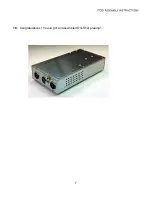
13.
Use the remaining 1/8” screws to assemble the
chassis.


