4
Assembly
5.
Before you begin, carefully unpack the kit and examine the parts. Check the contents of
each small bag against the BOM to make sure all the parts have been included. If you
think something’s missing, please e-mail the details to
and
we’ll ship replacement parts ASAP.
6.
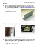
Arrange the chassis bottom on the bench as
shown. The bottom and top are identical,
except the bottom has more holes.
7.
If your module has an output transformer, select the appropriate mounting screws and run
them through the holes that align
with the circuit board. Use 4x 1½” screws for an N72.
Use 2x 1¼” for an A12B or J99B.
If you have an older module, you may have to drill your own holes.
8.
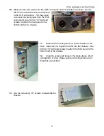
Slide ¼” nylon spacers over the screws and run them through the module PCB and output
transformer.
Don’t forget any spacers needed between the PCB and transformer. This
may require a bit of patience, but you only have to do it once.
9.
Run #4 keps nuts onto the screws coming through the top of the transformer as shown.
Leave the nuts a bit loose at this point.


