2
Instruction Conventions
Text in
orange
indicates a step where extra care needs to be taken. Doing it wrong isn’t a
disaster, but it’ll need to be corrected.
Text in
red
indicates a step that
must
be done correctly. Doing it wrong will guarantee
improper operation, and probably damage components and/or the circuit board.
Prepare the Module
The OneShot power supply board includes three relays that enable several optional features.
To take advantage of these features, most current preamp modules will require some
modifications. If you are not comfortable referring to the schematics, removing parts, wiring
jumpers, and possibly cutting PCB traces,
do not attempt these modifications yourself
.
You can always use the DI by using an external XLR jumper between the DI output and
preamp input if you do not want to make modifications to your module.
1.
DI Switching
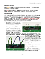
. To enable this feature,
the signal flow from the module’s input
connector must be interrupted and
rerouted to the
M+
and
M-
pads on the
OneShot power board. For most
modules, the easiest way to get the
signal from the module to the OneShot is
to remove the blue EMI filters. Solder
jumpers between the vacant filter pads
and the
M+
and
M-
pads as shown.
Make sure you’re using the pair of pads that connect back to the female XLR. Be sure to
observe proper polarity.
Consult the schematic and use your meter.
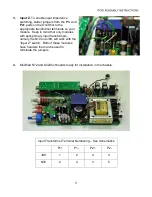
To get the signal
back to the module, solder jumpers
between the
P1+
and
P2-
pads and the
vacant filter pads as shown. The J99
and N72 have headers that can be used
to terminate the jumpers. For a more
permanent installation, solder directly to
the transformer pins as shown on the
next page.
2.
Pad
. The input pad attenuates
the microphone signal by 20dB.
Activating the pad increases the load on
the microphone, which can cause
changes in tone. The modifications for
DI switching also enable the pad.


