5
26
1
4
"
20
5
16
" 11
7
16
"
25mm
1"
5
5
8
"
7"
1
15
16
"
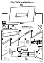
Top Leveling
Screws
Allows for leveling
adjustments of the
TV after mounting.
Tilt Locking Bolts
Allows for tilt
angle of the TV
adjustment.
Mounting Slots
Allow for a
variety of stud
configurations
and lateral shift
adjustments
when mounting
your TV.
Bottom Locking Screws
Prevents the TV from being
removed or dislodged from
the mounting plate.
Cable/Electrical Cut Out
A large opening on the
mounting plate allows
for easy cable access
and power distribution
installations.
Directional
Mounting
Arrows
The arrow
lets you know
which edge
is up.
Features