background image

Page

23

110124

411206

401430

411206

110124

401387

110208

1315

110165

110115

401557

401411

401391

401497

110116

411207

110117

401557

401411

110206

110153

110115

401379

411206

411206

411253

110117

401455

411187
110409

110410

401387

110208

1315

110165

110108

401363

401410

1397

401615

110109

110221

110222

401410

401611

401614

401613

401615

401614

401612

401409

411253

401430

110116
401358

411187

411187

110116

401358

110409

110409
110409

110410

401454

1314

401406

110208

401407

110153

110162

401409

401381

401394

110410

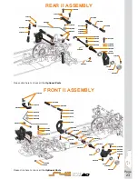
REAR II ASSEMBLY

FRONT II ASSEMBLY

Please click here to check all the 

Optional Parts


Please click here to check all the 

Optional Parts


Summary of Contents for Eryx 411 4.0

Page 1: ...INSTRUCTION MANUAL REFERENCE GUIDE ...

Page 2: ...il Serpent direct info serpent com The Serpent Facebook Twitter and Youtube pages give additional means of support and communications Safety Read and take note of the Read this First section before proceeding to assemble the car kit This car kit is intended for persons aged 16 or older Read this first This is a highly technical hobby product intended to be used in a safe racing environment This ca...

Page 3: ...oup of items within lines should be assembled first Direction the item should be moved Glue one item to another Press Insert one item into another Connect one item to another Gap between two items Apply transmission grease Grey threadlock Blue CA glue Red or silicone grease Orange Items not included Step number the order in which you should assemble the indicated parts 1 HOW TO USE THE MANUAL Appl...

Page 4: ...l so the cross pins are just covered DO NOT overfill NOTE In step 2 to mount the pin first put the pin in the purpose made slot as shown and after slide it through the hole in the shaft 3 1 4 1 4 2 3 2 2x10 2x10 5x15x0 2 5x15x0 2 4x10x0 2 Use some grease during assembly Use some grease during assembly 3 1 2 2 M2 5x8 wide thread NOTE The diff assembled as shown here should weigh max 11 4 grams ...

Page 5: ...5 STEP 5 STEP 6 STEP 7 3 1 2 M3x6 M3x6 M3x8 M3x6 M3x6 M3x6 7 2 3x5x2 3x5x1 3x5x2 3x5x1 Type 0 5 1 5 Spacer 0 5mm Spacer 0 5mm Type 0 5 1 5 7 1 M3x8 M3x8 M3x8 Note Orientation of the brakets 0 5 outside Bag 1 ...

Page 6: ... 9 1 10x15x4 10x15x4 10x15x4 10x15x4 1 1 1 2 2 2 2 3 3 M3x8 M3x8 M2 5x6 M3x8 M3x8 Note 1 Mount the gear washer correctly 2 DON T use glue Note orientation of the excenters Note orientation of the excenters 9 1 9 2 Bag 2 ...

Page 7: ...Page 7 STEP 10 STEP 11 STEP 12 M2 5x6 M3x8 M3x8 10 1 10 2 10 3 12 1 12 2 R4 26 mm M3x5 M3x5 5x8x2 5 5x8x2 5 Bag 3 ...

Page 8: ...EP 13 STEP 14 14 2 13 1 13 2 14 1 21 mm 3x5x1 M3x6 M3x6 3x5x0 3 M3x8 M3x6 12 3 3x5x2 3x5x2 Type 0 5 1 5 Type 0 5 1 5 Spacer 0 5mm Spacer 0 5mm Spacer 0 5mm 3 1 2 Note Orientation of the brakets 1 5 outside Bag 4 ...

Page 9: ...Page 9 STEP 15 15 1 15 2 15 3 M3x10 M3x6 M3x8 M3x8 M3x8 M3x6 3X5X2 3X5X1 3X5X1 3X5X1 3X5X1 M3x6 M3x6 M3x6 1 1 2 3 2 ...

Page 10: ...ge 10 STEP 16 STEP 17 17 1 17 2 17 3 24 mm 16 2 16 1 3 1 1 1 4 2 2 2 3 3x5x1 3x5x2 M2X5 M3X2 5 M2 3X4 2X10 2X10 6X12 5X10 Note the default position in the upright of the rear camber link pivot ball Bag 5 ...

Page 11: ... 19 1 19 2 M3X3 M3X3 M3X3 M3X4 M3X8 M3X8 M3X4 Do not overtighten M3x4 set screws to keep a free rotation of the anti roll bar Do not fully tighten M3x3 set screw till the anti roll bar will be assembled and correctly placed in step 19 2 M3x12 ...

Page 12: ...mall clip Big clip 1 7x8 5 3x5x2 1 1 2 3 4 5 1 2 2 3 5x10x4 8x12x3 5 M2x5 Note These double joint cardans come pre assembled in the kit Please just keep this step as a reference Note the default position in the bracket of the rear camber link pivot ball 9 mm Bag 6 ...

Page 13: ...rtighten M3x4 set screws to keep a free rotation of the anti roll bar Do not fully tighten M3x3 set screw till the anti roll bar will be assembled and correctly placed in step 19 2 1 1 2 2 3 M3X3 M3X3 M3X8 M3X8 4 M3X4 Note the default position in the steering block of the rear steering link ...

Page 14: ... supplied shock absorber oil 500 cst as default BLEEDING Slowly move the shockrod up and down to let all airbubles escape 26 1 26 2 26 3 26 4 The kit includes shock pistons with 1 2 3 and 4 holes Use as default 3 holes shock pistons 3x5x1 3x5x1 3x5x2 Note the default position in the bracket of the front camber link pivot ball 25 1 25 2 11 mm Shock Bag ...

Page 15: ...nt should hit the shock bottom If not re open the shock and let some oil bleed out and repeat the steps Allow some rebound on the shockshaft around 4mm is normal Measure fully extended 26 5 26 6 Insert the o ring inside the spring nut Assemble the spring nut 26 7 Assemble the spring and springcup to complete the shock M3x6 M3x6 Bag 7 ...

Page 16: ...Page 16 STEP 30 STEP 29 M3x5 M3x5 M3x5 M3x8 M3x8 2x10 2x10 M3x5 1 2 3 4 Default front upper shocks position Default rear upper shocks position ...

Page 17: ...Page 17 STEP 32 STEP 33 STEP 31 2x10 2x10 M3x8 M3x10 M3x10 M3x10 M3x8 M3x8 Nylock nut M3 1 1 1 2 2 2 3 3 ...

Page 18: ...EP 36 Pinion is NOT INCLUDED in the kit Assemble the proper pinion for your set up M3x10 M3x6 M3x6 M3x6 M3x6 M3x6 NOT INCLUDED NOT INCLUDED NOT INCLUDED Tip Use double sided tape to mount the ESC and RX to the chassisplate Bag 8 ...

Page 19: ...can be moved 3mm M3x5 M3x5 1 1 2 2 M3x5 M3x5 NOTE 3mm battery position adjustment Use battery REARWARD position as DEFAULT NOT INCLUDED NOTE Use glass tape not included to fix the battery to the chassis Nut M4 Flanged Nut M4 Flanged NOT INCLUDED NOT INCLUDED ...

Page 20: ...BLY 21 FRONT SOLID ASSEMBLY 21 MID AXLE ASSEMBLY 21 SHOCKS ASSEMBLY 21 REAR I ASSEMBLY 22 FRONT I ASSEMBLY 22 REAR II ASSEMBLY 23 FRONT II ASSEMBLY 23 STEERING ASSEMBLY 24 FRONT STEERING AND BUMPER ASSEMBLY 24 REAR SHOCK ASSEMBLY 25 FINAL ASSEMBLY 25 ...

Page 21: ...n TC 160300 Spring white 160301 Spring yellow 160302 Spring orange 160303 Spring red 160304 Spring Pink 160305 Spring blue 160306 Spring purple 160310 Spring set L23 5x2 160142 Shock onroad big bore piston 1 hole 2 160143 Shock onroad big bore piston 2 hole 2 160144 Shock onroad big bore piston 3 hole 2 160145 Shock onroad big bore piston 4 hole 2 120007 Spur gear 64P 100T 120008 Spur gear 64P 104...

Page 22: ...401392 110157 401399 1311 401351 110157 401399 411063 1344 1344 1311 110130 401604 401024 110410 401391 411207 401630 110124 110124 REAR I ASSEMBLY FRONT I ASSEMBLY 411253 110114 110114 110410 401403 110410 110409 110409 401597 401586 401024 401024 401605 110114 401426 401420 1652 110122 110122 110104 110104 Please click here to check all the Optional Parts ...

Page 23: ...1387 110208 1315 110165 110108 401363 401410 1397 401615 110109 110221 110222 401410 401611 401614 401613 401615 401614 401612 401409 411253 401430 110116 401358 411187 411187 110116 401358 110409 110409 110409 110410 401454 1314 401406 110208 401407 110153 110162 401409 401381 401394 110410 REAR II ASSEMBLY FRONT II ASSEMBLY Please click here to check all the Optional Parts Please click here to c...

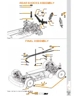
Page 24: ...89 110183 110108 110122 401401 110408 401588 110409 411187 411206 401429 411253 110410 110124 401372 401372 110122 110122 110208 802211 1667 110109 401628 401357 401628 802211 401361 110104 110402 110128 110128 110122 160135 401631 1652 110109 110122 110122 401634 110108 411206 401429 Please click here to check all the Optional Parts ...

Page 25: ...110124 110124 110122 110128 802361 802361 110208 1652 1652 802361 401495 1606 401413 110128 401627 401627 401627 401627 401413 110128 110108 110108 110452 110157 110157 110108 110208 802361 110128 160135 Please click here to check all the Optional Parts ...

Page 26: ...Page 26 TEAM SERPENT NETWORK website and blog ERYX 4 0 SPARE PARTS ERYX 4 0 OPTIONAL PARTS SERPENT TOOLS SERPENT MERCHANDISING social media ...

Page 27: ...Page 27 NEWS NOTES ...

Page 28: ...www serpent com info serpent com S411 Eryx 4 0 manual V1 ...

Reviews: