2
SERIAL CABLES NVMe JBOF User’s Manual
2.
H
ARDWARE
I
NSTALLATION
This section gives the layout of the panel and describes the procedures for setting up the
PCI-ENC8G-024U enclosure.
2.1 Panel
Layout
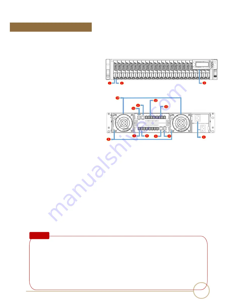
1. Activity indicator LED
‧
Flash Blue – Access
‧
Red – HDD failure
2. SSD presence LED
‧
White – Power On
3. LCD module
4. Power cord receptacle
5. Fan status LED
‧
Normal – No light
‧
Failure – Red
6. Mute button
‧
To mute buzzer beeping of enclosure failure
7. Port Link w idth indication LED
‧
One Red LED– configure as one x16 port
‧
Two Red LEDs
—
configure as two x8 ports
8. Upstream/Downstream port indication
‧
Flash Blue – Downstream port
‧
Blue – Upstream port
9. LAN port
10. USB port
11. System healthy LED
‧
Green – Normal
‧
Red – Failure events occurred
12. Quad port mini-SAS HD (SFF-8644) connector
13. Quad port mini-SAS HD (SFF-8644) connector
14. Swappable fan
Note :
When any one of environmental sensors is abnormal or there is a drive status failure, the
buzzer on the PCI-ENC8G-024U switch board will beep. To mute the buzzer, press the mute
button near LAN port at the rear of the enclosure. Environmental sensors include:
Cooling elements (Fan)
i.
Temperature elements
ii.
Voltage elements
iii.
Current element
iv.
Power Supply element


