


27
27
AsteRx-i UAS (PRELIMINARY)
27
5.1
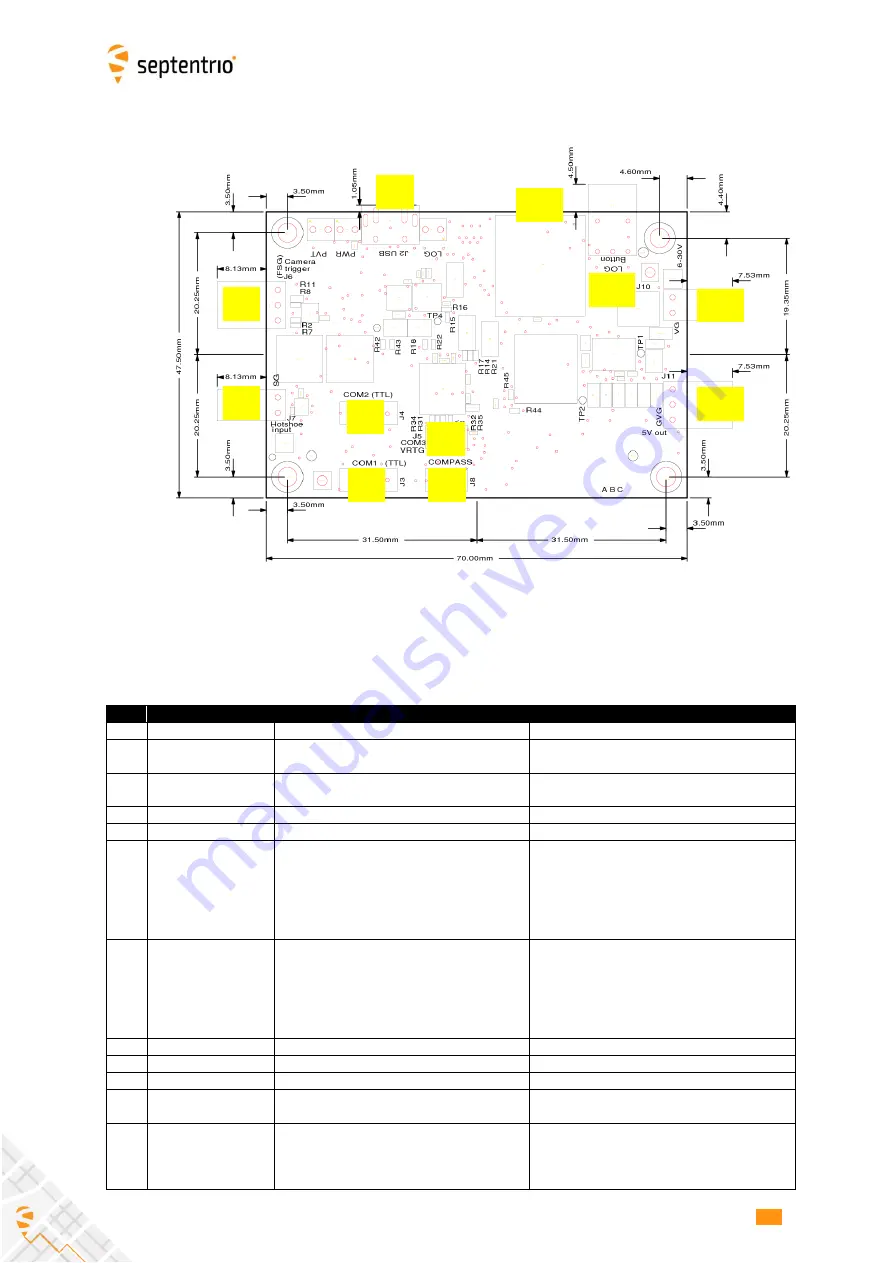
Connectors
ID
Type
Description
Usage Example
J1
30-pin DF40C
Connector to the AsteRx-i OEM board
J2
Micro B USB
USB interface to AsteRx-i OEM
Connect to laptop or PC to power the system
and control the AsteRx-i.
J3
DF13-6P-1.25DSA
COM1 TTL UART from AsteRx-i OEM.
Pin#1 is a 5V power input
J4
DF13-6P-1.25DSA
COM2 TTL UART from AsteRx-i OEM.
J5
DF13-4P-1.25DSA
COM3 RS-232 UART from AsteRx-i OEM.
Connect to IMU
J6
.1" RA Header 1x3
Pin#2 (Shutter) is connected to ground for
30ms starting at the rising edge of the PPS
pulse from the AsteRx-i OEM. Otherwise it
is floating.
Pin#3 (PPS out) is the PPS out signal from
the AsteRx-i OEM (3.3V level)
Connect Pin#3 to the sync input of the IMU
J7
.1" RA Header 1x2
3.3V-LVTTL event input. Connects to the
EventA pin of the AsteRx-i OEM through an
inverter. A high-to-low transition at the J7
connector corresponds to a low-to-high
transition as seen by the AsteRx-i OEM and
vice versa.
This header can for example be connected to
the flash port of a camera (e.g. via Hot Shoe
or Prontor-Compur interface), to allow the
AsteRx-i OEM to time tag the pictures and
provide the position at the exact time the
picture was taken.
J8
DF13-4P-1.25DSA
Reserved
J10
.1" RA Header 1x2
6-30V DC supply
Can be directly connected to a battery pack.
J11
.1" RA Header 1x3
5V DC out (max 2A)
Connect to the IMU
J12
DM3AT-SF-PEJM5
µSD-card socket for GNSS measurement
logging
J13
.1" V Header 1x2
Connects to the Button pin of AsteRx-i OEM Push-button to start/stop logging and
mount/unmount the SD-card. The interface
board contains a debouncing circuit. See
section 2.9.
J2
J6
J7
J4
J3
J8
J5
J11
J10
J13
J12