background image

www.sentera.eu

MIW-RTVS1-EN-000 - 03 / 11 / 2020

9 - 12

back to the table of contents

TRANSFORMER FAN SPEED CONTROLLER WITH 
MODBUS RTU COMMUNICATION

RTVS1

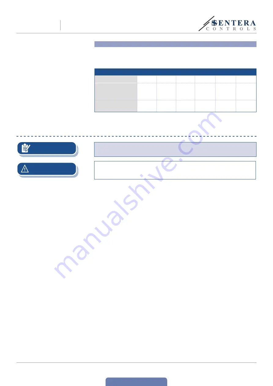
Voltage steps selection

The standard configuration of the output voltages automatic mode is as indicated 
in 

Table 1

 below.  The threshold levels at which each step activates is selected via 

Modbus holding registers from 21 to 25. Each of these levels  represents the value 
above which step is activated. 

Table 1 Voltage steps

Steps*

0

1

2

3

4

5

Auto forward 

mode default 

values

0 %

17 %

34 %

51 %

68 %

85 %

Auto reverse mode 

default values

-

0 %

75 %

50 %

25 %

1 %

* Each level can take a value from  0 to 100 %. 

OPERATING INSTRUCTIONS

NOTE

On start-up the green COM LED blinks fast  for 15  seconds to indicate that the 
device is initialising. 


Make sure the connections are correct before you power the unit.


 Make sure the mains supply voltage is within the admissible rated maximum 
current of the product.

ATTENTION

1. 

Switch off the mains power supply before connecting any power cables.

2. 

 Install the connected sensor in an appropriate zone in order to measure the 
relevant ambient conditions.

3. 

 Select the operating mode via Modbus Holding Register 11. The default mode is 

Automatic forward mode

.

3.1 


Manual mode


The value is taken by Holding Register 12, where you can set the desired 
output  step (see the steps and corresponding voltages in Table 1 above.)

3.2 


Automatic modes 

 When Auto mode has been selected, the controller  changes the five 
speeds automatically according to the values measured by the sensor 
connected to the RJ45 master socket. There are two automatic modes:

3.2.1 


Automatic forward mode. See operational digram below: 

Each level can take value from  0 to 100 % with the 
following restrictions: 0 = OFF, i.e. the step is skipped. 
For example:  Step 1 = 17 %, Step 2 = 34 %, Step 3 = 
0 %, Step 4 = 68 %, Step 5 = 85 %, from 34 to 68 % 
the device will be in Step 2 and above 68% - in Step 4. 
Each step threshold restricts by the steps above and below with 
minimum of 11% difference, so when the hysteresis is set at 10% 
the thresholds  will not overlap. For example: Step 1 = 17 %, Step 2 
= 34 %, Step 3 = 51 %, Step 2 can take values from 28 % to 40 %. 
The Hysteresis delta is asymmetric, valid when the input value is 
transitioning from high to low values. The device will subtract the value of Δ 
from the step threshold and the step will change below the resulting value.  
For example: Step 3 = 51 % threshold, Hysteresis delta = 
2 %, Step 3 will be ON above 51% and OFF below 49 %. 


An example of forward switching mode when Min 
Step = 0 and Max Step = 5 is given in 

Fig. 4

 below. 


The thresholds are at 17 % and hysteresis delta is set from 2 to 10 % 
via Holding Register 16 (see 

Fig. 4

).

Summary of Contents for RTVS1

Page 1: ...Mounting and operating instructions TRANSFORMER FAN SPEED CONTROLLER WITH MODBUS RTU COMMUNICATION RTVS1 ...

Page 2: ...SCRIPTION 4 ARTICLE CODES 4 INTENDED AREA OF USE 4 TECHNICAL DATA 4 STANDARDS 4 WIRING AND CONNECTIONS 5 MOUNTING INSTRUCTIONS IN STEPS 6 OPERATING INSTRUCTIONS 9 VERIFICATION OF INSTALLATION 11 TRANSPORT AND STORAGE 12 WARRANTY AND RESTRICTIONS 12 MAINTENANCE 12 TRANSFORMER FAN SPEED CONTROLLER WITH MODBUS RTU COMMUNICATION RTVS1 ...

Page 3: ...t is as dry as possible avoid condensation All installations shall comply with local health and safety regulations and local electrical standards and approved codes This product can only be installed by an engineer or a technician who has expert knowledge of the product and safety precautions Avoid contacts with energised electrical parts Always disconnect the power supply before connecting servic...

Page 4: ...mounted Selection can be made via RTVS1 Modbus holding register 20 TECHNICAL DATA Supply voltage 230 VAC 50 60 Hz Modbus RTU communication TK monitoring for thermal motor protection Operating modes Automatic from low to high or from high to low Fan speed based on input from external Sentera sensor or potentiometer connected to the RJ45 master socket Manual Fan speed based on user input via Modbus ...

Page 5: ... be activated manually via Modbus Holding register 14 or automatically in case of an RTVS1 alarm L N INPUT Power supply neutral L Power supply phase 230 VAC 50 60 Hz TK Input TK monitoring for thermal motor protection TK RJ45 master socket to connect a Sentera HVAC transmitter for demand based fan speed control in automatic mode Pin 1 24 VDC Supply voltage Pin 2 Pin 3 A Modbus RTU communication si...

Page 6: ...he warmer the device will get For example in a technical room the correct installation height can be of great importance Do not install the controller above heating equipment or heat sources 3 3 If maximum ambient temperature cannot be adhered to please provide extra forced ventilation cooling Not respecting the abovelisted rules can reduce service life and relieves the manufacturer of any respons...

Page 7: ...the 3SModbus software or Sensistant For the default factory setting see the Modbus register map The desired fan speed can be adjusted via Modbus holding register 14 For the complete Modbus register data refer to the product Modbus Register Map which is a separate document attached to the article code on the website and contains the registers list NOTE Optional settings 1 In automatic mode a Senter...

Page 8: ...lled on your computer The Modbus to USB converter CNVT USB RS485 allows you to connect a Sentera device to the USB port of your computer and to monitor or adjust the different parameters see Application examples 1 and 2 Application example 1 Manual mode control via Modbus holding register 14 CNVT USB RS485 Master RTVS1 A B GND Application example 2 Automatic mode demand based ventilation RTVS1 Sla...

Page 9: ...orward mode 3 1 Manual mode The value is taken by Holding Register 12 where you can set the desired output step see the steps and corresponding voltages in Table 1 above 3 2 Automatic modes When Auto mode has been selected the controller changes the five speeds automatically according to the values measured by the sensor connected to the RJ45 master socket There are two automatic modes 3 2 1 Autom...

Page 10: ... diagram below for an example with steps from 2 to 5 An example of Auto Reverse mode the steps threshold configuration is as follows Step 1 0 Step 2 75 Step 3 50 Step 4 25 Step 5 1 can be as low as 0 1 is given in Fig 5 below When the Input value is above 1 device switches to Step 5 above 25 Step 4 above 50 Step 3 above 75 Step 2 up to 100 When the Input value decreases the hysteresis delta is sub...

Page 11: ... the sensor if sensor is lost the article stays on the last step selected If both communications are lost device stays on the last step selected In Auto modes if there is no communication to the control monitoring station the article continues to operate autonomously while the sensor is connected 18 Sensor output register value number Select which sensor output will be used as input to the device ...

Page 12: ...n manufacturing Any modifications or alterations to the product after the date of publication relieve the manufacturer of any responsibilities The manufacturer bears no responsibility for any misprints or mistakes in this data MAINTENANCE In normal conditions this product is maintenance free If soiled clean with a dry or damp cloth In case of heavy pollution clean with a non aggressive product In ...

Reviews: