CamCor CT and PRO Series Hardware User Manual
B-7
Appendix B
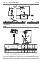
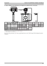
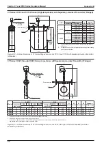
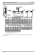
CT Series CC025 through CC080 Sensor (High-temp.) with Separately-mounted Transmitter (Flanged)
A
W
h1
10
H
107
98
L
Terminal box
Ground screw
Conduit connection
3/4-14 FNPT
(M25)
Model
ASME
DIN
H
(mm)
h1
(mm)
A
(mm)
W
(mm)
Approx.
Weight (kg)
Nominal size
(mm)
150
300
600
900
Nominal size
(DN)
PN 10, 16
PN 25, 40
L (mm)
L (mm)
CC025
25
411
424
437
N/A
25
376
380
638
329
83
262
10.9
CC040
40
547
560
575
N/A
40
507
513
768
452
121
385
20.3
CC050
50
550
563
582
N/A
50
513
519
20.7
CC080
80
699
717
737
777
80
659
675
960
602
174
510
54.1
1. Conduit connections are 3/4-14 FNPT for CSA units and M25 for ATEX units.
2. ASME 900 flanges are only available in Alloy C22 material.
• DIN flanges are only available for meter material SUS316L.
Figure B.10—Outline dimensions of CT Series flanged sensor units CC025 through CC080 with separately-mounted
transmitter (millimeters)
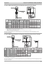
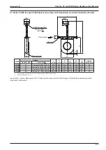
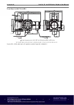
CT Series CC025 through CC080 Sensor with Heat Tracer and Separately-mounted Transmitter (Flanged)
A
W
h1
10
H
107
98
L
Terminal box
Ground screw
Conduit connection
3/4-14 FNPT
(M25)
Conduit connections are 3/4-14 FNPT for CSA units and M25 for ATEX units.
Ah
Wh
h2
A1
Lh
Heat retention fluid inlet
10 stainless pipe
Heat retention fluid outlet
10 stainless pipe
M6 bolt
(for holding
heat tracer)
Flow direction
Flow direction
Model
Nominal
size (mm)
Heat Tracer Model
Compatibility
Lh
(mm)
h2
(mm)
Ah
(mm)
A1
(mm)
Wh
(mm)
Approx. Weight
(kg)
CC025
25
HT1-025A
254
340
106
56
268
16.9
CC040
40
HT1-040A
376
464
144
70
390
31.8
CC050
50
HT1-040A
376
464
144
70
390
32.2
CC080
80
HT1-080A
501
612
198
110
545
75.1
Figure B.11—Outline dimensions of CT Series flanged sensor units CC025 through CC080 with heat tracer and separately-
mounted transmitter (millimeters)
Summary of Contents for CamCor CC001
Page 14: ...14 CamCor CT and PRO Series Hardware Manual Section 3 This page is left blank intentionally ...
Page 24: ...24 CamCor CT and PRO Series Hardware Manual Section 3 This page is left blank intentionally ...
Page 54: ...54 CamCor CT and PRO Series Hardware Manual Section 5 This page is left blank intentionally ...
Page 62: ...62 CamCor CT and PRO Series Hardware Manual Section 7 This page is left blank intentionally ...

