CamCor CT and PRO Series Hardware Manual
115
Section 10
115
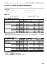
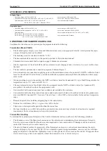
ATEX/IECEX (PRO SERIES)
Integral type
• Transmitter ratings: II 2G Ex d ib IIB T4 Gb
• Sensor ratings: II 2G Ex ib IIB T4 Gb
• Transmitter and sensor ambient temperature: –40°F to 131°F (–40°C to 55°C)
• Sensor to be connected: CP006 to CP050
• Fluid temperature: –40°F to 158°F (–40°C to 70°C) for CP015
–40°F to 176°F (–40°C to 80°C ) Other than CP015
• Communication: HART, Modbus
Separate type
• Transmitter ratings: II 2G Ex d [ib] IIC T6 Gb
• Sensor ratings: II 2G Ex ib IIB T3, T4
• Transmitter ambient temperature.: –40°F to 131°F (–40°C to 55°C)
• Sensor to be connected: CP006 to CP050
• Fluid temperature:
Temp. Class 3: −40˚F to 257˚F (40˚C to 125˚C) All models
• Sensor ambient temperature: −40˚F to 140˚F (−40˚C to 60°C)
Temp. Class 4: –40°F to 158°F (−40˚C to 70˚C) for CP015
–40°F to 176°F (–40˚C to 80˚C) Other than CP015)
• Communication: HART, Modbus
CONDITIONS FOR HAZARDOUS AREA USE
Conditions for the safe use of explosion-proof equipment include the following:
Transmitter (Model PA0K)
•
The threaded (glass) display cover, threaded (blind) terminal cover, and spigot joint side lid. which provide the explo
-
sion-proof integrity, must not be altered.
•
The fastening screw for the side lid shall be “A-50.”
•
The transmitter shall be used only in the position specified in the instruction manual.
•
Threaded electrical conduit shall complete engage 8 threads at a minimum.
•
Electric capacitance of the label shall be 1nF maximum to avoid charging of static electricity. Use a wet cloth to clean
the label.
•
The transmitter is permanently connected equipment, Pollution Degree 2.
•
Line and neutral pole connections supplying power at the installation site must be protected by NRTL certified or listed
fuses for Canada and US rated 2A max, installed outside the equipment and acceptable to the authorities where equip
-
ment is sold.
•
Wiring providing power to the unit must be NRTL certified or listed for Canada and US –type Field Wiring suitable for
temperatures above 75°C and size AWG 14-16.
•
The user-replaceable mains fuse found within the equipment must be NRTL certified or listed for Canada and US
acceptable to the authorities where the equipment is sold.
•
Units installed with conduit runs must have conduit seals installed at the enclosure.
•
Units installed with other than conduit runs and conduit seals, must be fitted with certified or listed cable glands evalu
-
ated to ASME/UL Standard 2225 for use in “Class I, Zone 1, AEx d IIB” or better suitable for the ambient temperature
range.
•
Remove adapter before installing stopping plug in the conduit entry.
•
Terminal cover fasteners (M6 x 1 - 6g) are class A-50 or better.
•
There are no other replaceable parts other than the mains fuse.
•
If at any time there is a conflict between the system safety provisions and any relevant local (national or regional)
requirements, the local requirements always take precedence.
Transmitter Handling
To maintain the explosion-proof integrity of the CamCor transmitter enclosure, adhere to the following guidelines:
•
The threaded covers of the flameproof enclosure are the critical parts in maintaining the explosion-proof integrity.
Exercise care to ensure that the threads are not damaged and do not contain debris. If damage or debris is detected,
contact the Cameron service center nearest you.
•
The side lid (bonded surface of spigot joint) of the flameproof enclosure is a critical part in maintaining the explo
-
sion-proof integrity. Do not open this lid. If it is accidentally opened during maintenance, exercise care to avoid dam
-
aging it and protect it from debris. Tightening screws of strength class A-50 are used on the side lid. If it appears these
screws are missing or have been replaced, contact the Cameron service center nearest you.
Summary of Contents for CamCor CC001
Page 14: ...14 CamCor CT and PRO Series Hardware Manual Section 3 This page is left blank intentionally ...
Page 24: ...24 CamCor CT and PRO Series Hardware Manual Section 3 This page is left blank intentionally ...
Page 54: ...54 CamCor CT and PRO Series Hardware Manual Section 5 This page is left blank intentionally ...
Page 62: ...62 CamCor CT and PRO Series Hardware Manual Section 7 This page is left blank intentionally ...

