LSP 500 PRO
Wireless Integrated PA System
Instruction manual
Page 1: ...LSP 500 PRO Wireless Integrated PA System Instruction manual...
Page 2: ...alling devices in the expansion slots 20 Operating the LSP 500 PRO via a tablet 23 The operating menu 28 Menu structure 28 Equalizer 29 Master EQ 30 EQ presets for the inputs 31 Virtual Bass 32 Compre...
Page 3: ...10 Protect the power cord from being walked on or pinched particularly at plugs convenience receptacles and the point where it exits from the apparatus 11 Only use attachments accessories specified b...
Page 4: ...he sound pressure corresponding to the maximum permissible volume which is by law in some countries allowed to affect your hearing for the duration of a working day It is used as a basis according to...
Page 5: ...o not continue to use defective rechargeable batteries When not using rechargeable batteries for extended periods of time charge them regularly about every three months Do not mutilate or dismantle Ke...
Page 6: ...ory our culture of innovation and our passion for excellence With our audio experience of more than 60 years we have designed this LSP 500 PRO as a portable professional sound system for annual meetin...
Page 7: ...ount ears for Sennheiser evolution wireless G3 devices 1 dust cover 1 quick guide 1 safety guide 1 CD ROM A list of accessories can be found on the LSP 500 PRO product page at www sennheiser com and o...
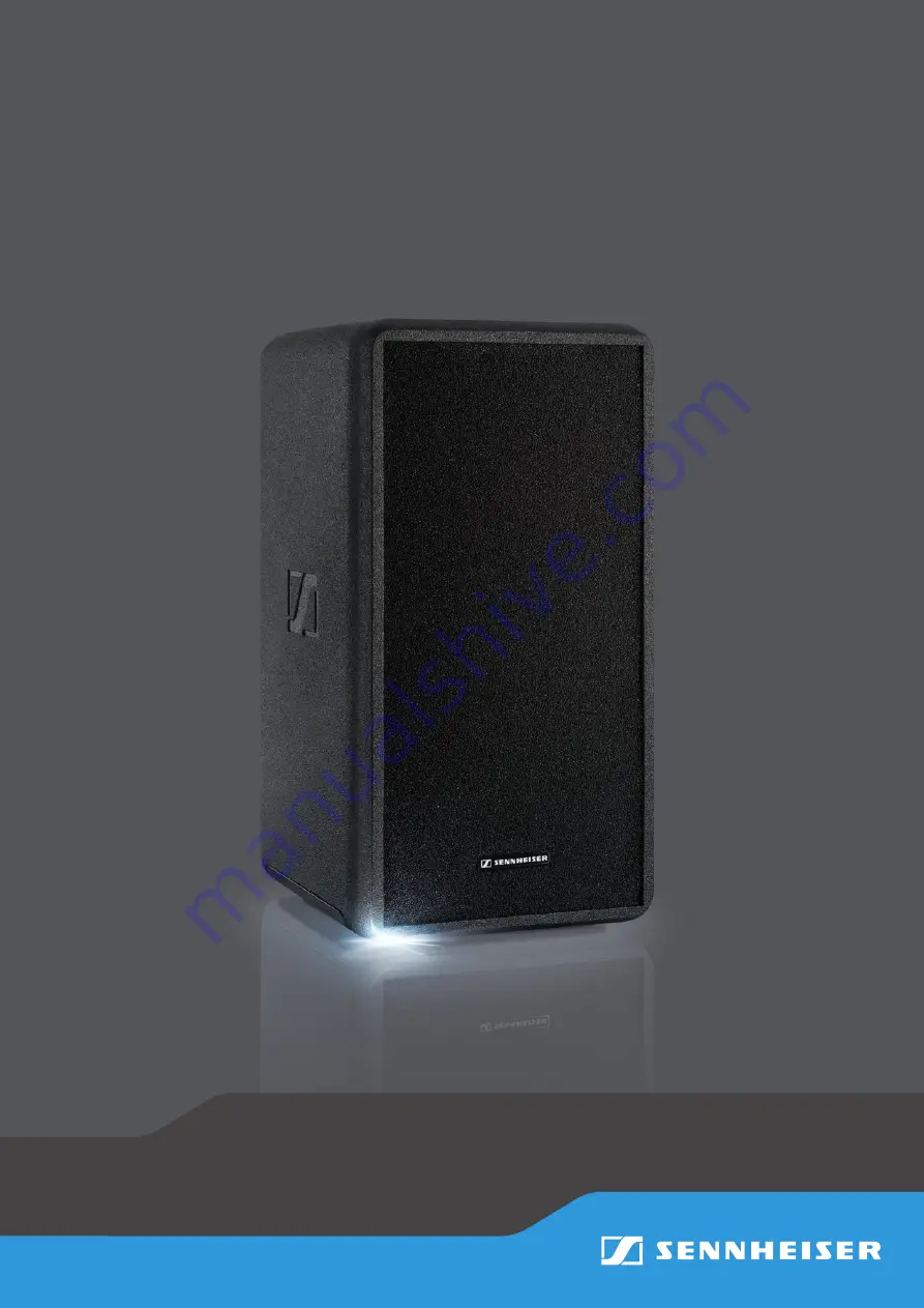
Page 8: ...erview Product overview B 1 5 3 2 1 4 A C A Front view B Rear view 1 Carrying handle 2 Expansion slots from top to bottom slot 1 slot 2 slot 3 3 Operating elements see page 9 4 Battery compartments C...
Page 9: ...l 9 MENU control jog dial 0 MIC input control jog dial A MIC input XLR 3F 6 3 mm jack combo socket B AUX IN input control jog dial C AUX IN input RCA socket D USB input control jog dial E USB port F L...
Page 10: ...d For the specifica tions of the pole mount refer to page 61 CAUTION Danger of injury and material damage due to tipping dropping of the product X X When mounting the LSP 500 PRO secure it against tip...
Page 11: ...ension cables with protective ground contacts Connecting the LSP 500 PRO to the mains power supply X X Make sure that the POWER on off switch L is set to position X X Connect the mains cable to the ma...
Page 12: ...To remove the battery pack from the battery compartment X X Open the cover of the battery compartment see fig X X Pull the battery pack out of the battery compartment using the recessed grip see fig T...
Page 13: ...tery charge status display refer to page 16 X X Only remove the battery pack that is not in use Deep discharge protection The battery packs have a deep discharge protection When unused for extended pe...
Page 14: ...wered For that to happen the battery packs must be inserted and charged To switch the LSP 500 PRO on X X Set the POWER on off switch L to position X X The LSP 500 PRO switches on The operation indicat...
Page 15: ...ons of the SLOT 1 2 3 6 MIC 0 AUX IN B USB Djog dials Action Icon Function Turn a jog dial Adjusts the input volume of the corresponding input Press a jog dial Activates a function Functions of the MA...
Page 16: ...pacity of 50 The battery pack in the right battery compartment is fully charged and is currently not in use The right battery compartment is empty The battery pack in the left battery compartment is i...
Page 17: ...storing the settings made When navigating the operating menu the escape function also allows you to return to the previous menu level X X Press the SLOT 1 jog dial to call up the escape function and...
Page 18: ...u turn or press a jog dial when the lock mode is activated locked is also briefly displayed However when the lock mode is activated the POWER on off switch can still be used Deactivating the lock mode...
Page 19: ...con necting wired audio sources e g microphone instrument The MIC input provides a switchable 48V phantom power The phantom power can be activated via the menu AUX IN RCA input for connecting wired au...
Page 20: ...llation For more infor mation refer to page 53 CAUTION Danger of electric shock X X Before installing devices in the expansion slots switch the LSP 500 PRO off and disconnect it from the mains power s...
Page 21: ...de of the receiver transmitter X X Secure the rack mount ears supplied with the LSP 500 PRO to the sides of the receiver transmitter using the previously removed 4 recessed head screws You require 2 r...
Page 22: ...nection sockets of the stereo transmitter refer to the corresponding instruction manual X X Connect the rod antennas of the receiver transmitter and align them in a V shape X X Make sure that the ante...
Page 23: ...common settings for several LSP 500 PRO at the same time The app supports the operation of up to 20 LSP 500 PRO simultaneously Information on downloading and installing the app as well as information...
Page 24: ...the desired position X X Tap on a box to edit the settings of this box X X Tap on the Select multiple option to select several boxes at the same time and to edit their common settings X X Tap on the S...
Page 25: ...on the Positioning screen you can configure the selected LSP 500 PRO The following screen appears Mixing Panel screen The Mixing Panel screen shows a summary of all activated inputs of all boxes You c...
Page 26: ...taneously select all boxes or you can tap on Select multiple to simultaneously select cer tain boxes Adjusting common settings for several boxes If you have selected several boxes on the previous scre...
Page 27: ...LSP 500 PRO 27 Operating the LSP 500 PRO via a tablet Equalizer You can operate the equalizer of the LSP 500 PRO via the app Compressor You can operate the compressor of the LSP 500 PRO via the app...
Page 28: ...r Slot 1 Master Slot 2 Slot 3 MIC AUX USB Bluetooth Compressor Slot 1 Slot 2 Slot 3 MIC Service System Info Maintenance Firmware Update Bluetooth Pairing Volume Delay USB Player Bluetooth Settings Ser...
Page 29: ...a master EQ for the overall signal of the LSP 500 PRO or you can open and configure an equalizer with 3 presets for each individual input SLOT 1 SLOT 2 SLOT 3 MIC AUX IN USB BLUETOOTH To open the equ...
Page 30: ...e cut off frequency of the high frequency band MIC Sets the level of the low frequency band AUX IN Sets the level of the mid frequency band USB Sets the level of the high frequency band X X Press the...
Page 31: ...cting an EQ preset for an input To select an EQ preset for an input X X Select the desired input in the EQUALIZER menu and turn the MENU jog dial until the EQ PRESETS menu item is displayed X X Press...
Page 32: ...r the inputs AUX IN USB and BLUETOOTH The virtual bass function uses the SRS WOW HD technology To switch the virtual bass function on or off X X At the first menu level turn the MENU jog dial until th...
Page 33: ...ifferent talking distances to the mic or different speakers 1 2 to 2 The rain reduction should be between 0 6 dB peak limiter compensate for sudden signal peaks e g due to throat clearing or touching...
Page 34: ...g dial until the DELAY menu item is displayed X X Press the MENU jog dial to open the DELAY menu item X X Turn the MENU jog dial to adjust a delay value The delay can be adjusted in the range from 0 t...
Page 35: ...ferent USB flash drives on the market in compatibilities may still occur even if the above requirements are complied with To open the USB player X X At the first menu level turn the MENU jog dial unti...
Page 36: ...SLOT 3 Changes to recording mode MIC Short press jumps to the previous track Long press rewinds the track AUX IN Browses through the playlist without stopping the current track AUX IN Play Pause USB...
Page 37: ...jog dial to end the recording and to change to playback mode X X Change from playback mode to recording mode X X Press the AUX IN jog dial to start the recording A new recording file is created The n...
Page 38: ...the MENU jog dial to choose between PAIRING and VOLUME X X Press the MENU jog dial to open the selected menu item Adjusting the volume for the Bluetooth interface To adjust the input volume for the B...
Page 39: ...uccessfullyestablished PAIRINGSUCCESSFUL appears on the display panel and the Bluetooth icon is displayed steadily in the status area When the Bluetooth connection is not made or after an automatic ti...
Page 40: ...the test sound X X In the SETTINGS menu turn the MENU jog dial until the TEST SOUND menu item is displayed X X Press the MENU jog dial to open the TEST SOUND menu item X X Turn the MENU jog dial to a...
Page 41: ...he LSP 500 PRO is available as a mono signal at the LINK OUT output and at the SLOT 1 expansion slot X X Select MASTER if you want to send the overall signal of the LSP 500 PRO to one or several LSP 5...
Page 42: ...erate the LSP 500 PRO via a tablet refer to page 23 Important information on WLAN operation In order for you to be able to operate the LSP 500 PRO in a wireless network the following requirements have...
Page 43: ...tween ON and OFF X X Press the MENU jog dial to activate your selection and to switch the WLAN function on or off When the WLAN function is switched on you can connect the LSP 500 PRO to a wireless ne...
Page 44: ...e MENU jog dial until the IP MODE menu item is displayed X X Press the MENU jog dial to open the IP MODE menu item X X Turn the MENU jog dial to choose between AUTO or FIX Option Function AUTO IP addr...
Page 45: ...o the previous menu level To change the IP address when FIX is the selected assignment mode X X In the WLAN menu turn the MENU jog dial until the IP ADDRESS menu item is displayed X X Press the MENU j...
Page 46: ...he previous menu level To change the IP subnet mask when FIX is the selected assignment mode X X In the WLAN menu turn the MENU jog dial until the IP NETMASK menu item is displayed X X Press the MENU...
Page 47: ...previous menu level To change the IP default gateway when FIX is the selected assignment mode X X In the WLAN menu turn the MENU jog dial until the IP GATEWAY menu item is displayed X X Press the MEN...
Page 48: ...ith a lock icon X X If the desired network does not appear in the list of networks press the SLOT 3 jog dial REFRESH function to run a new scan for available networks and to update the list X X Turn t...
Page 49: ...the cursor position SLOT 3 Deletes the character at the cursor position MIC Enters capital letters AUX IN Enters lower case letters USB Enters numbers and special characters X X Press the MENU jog dia...
Page 50: ...case letters USB Enters numbers and special characters X X Press the MENU jog dial to confirm the entry of the network key The connection to the network is now established This can take up to a minute...
Page 51: ...Changing the multicast address and port used by the LSP 500 PRO also requires changing the multicast address and port used by the iPad app iPad Settings LSP 500 PRO To change the multicast address and...
Page 52: ...C menu turn the MENU jog dial until the INPUT SENSITIVITY menu item is displayed X X Press the MENU jog dial to open the INPUT SENSITIVITY menu item X X Turn the MENU jog dial to choose between 20 dB...
Page 53: ...formed To start the device detection process X X In the Settings menu turn the MENU jog dial until the DEVICE DETECTION menu item is displayed X X Press the MENU jog dial to open the DEVICE DETECTION...
Page 54: ...en the RESET menu item X X Turn the MENU jog dial to choose between NO AUDIO and ALL X X Press the MENU jog dial to activate your selection Option Function NO No settings are reset AUDIO All audio set...
Page 55: ...ystem INFO menu item is displayed X X Press the MENU jog dial to open the System INFO menu item X X Open the Battery Info menu item The BATTERY INFO menu item contains the following sub menu items Men...
Page 56: ...item After approximately 8 seconds the following screen is displayed X X Press the USB jog dial to start the firmware update The firmware update may take several minutes After the update Success appe...
Page 57: ...damage the surface of the product X X Keep all liquids away from the product X X Do not use any solvents or cleansing agents X X Before cleaning switch the LSP 500 PRO off and disconnect it from the m...
Page 58: ...uction manual of the receiver The audio signal from a wireless microphone is too low The output volume of the installed receiver is too low Increase the output volume of the installed receiver instruc...
Page 59: ...he WLAN connection Divers causes Observe the information on WLAN operation page 42 A USB storage device cannot be detected or used The USB storage device is not formatted or not compatible Check if th...
Page 60: ...is not correct Enter the network key again page 50 No network found Check the available access points and their ranges Battery charge status 21 Replace the battery pack connect the LSP 500 PRO to the...
Page 61: ...tem closed Drivers woofer 8 tweeter 3 4 Sound pressure level max 110 dB SPL fullspace Frequency response 65 Hz to 18 kHz 10 dB Dispersion h x v 80 x 60 6 dB Electronics Amplifier Class D Output power...
Page 62: ...h Operating time approx 6 h speech approx 3 h per battery pack Charging time approx 5 h approx 2 5 h per battery pack Temperature Operation 0 C to 50 C 32 F to 122 F Storage 20 C to 70 C 4 F to 158 F...
Page 63: ...ies The following accessories for the LSP 500 PRO are available LAS 500 slip cover LAP 500 protective cover LAB 500 trolley bag LBA 500 battery pack Recommended accessories for the expansion slots Dev...
Page 64: ...ents CAN CSA C22 2 No 60065 03 and UL 60065 Trademarks Sennheiser is registered trademark of Sennheiser electronic GmbH Co KG Other company product or service names mentioned in this instruction manua...
Page 65: ...tested and found to comply with the limits for a Class B digital device pursuant to part 15 of the FCC Rules These limits are designed to provide reasonable protection against harmful interference in...
Page 66: ...Sennheiser electronic GmbH Co KG Am Labor 1 30900 Wedemark Germany www sennheiser com Publ 05 14 549168 A03...