12
A1 icon blinks, when Power key is pressed at Lock Blink Mode. It will be
converted to A1 Alarm Mode by pressing Power key, and the blinking icon will be
alternated in the sequence of A2, TWL, STEL and Password. If you want to approach
to each Alarm Value Set Mode, enter it by pressing Power key.
A1 icon blinks by pressing Power key at Lock Blink Mode. And it is converted
to %LEL Alarm Value Set Mode by pressing Power key again. After moving to %LEL
Alarm Value Set Mode, Alarm Value of %LEL, that has been input initially, blinks.
And the Alarm Value can be changed by the same method as password input.
Changing sequence of Alarm Value is %LEL, %vol, Oxygen, Carbon Monoxide and
Hydrogen Sulfide, and it returns to A1 Set Mode when the change of Alarm Value
of each gas is completed.
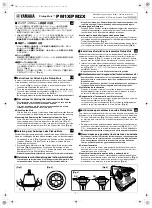
Alarm Set of Each Gas
…
Save value
Change value
Alarm Display
When A1 alarm occurs, and the operator recognizes it and presses Power key,
only the sound and vibration of alarm stop, remaining LED alarm as the operation
stale. When A2 alarm happens, the operator and workers should promptly escape
from the work site. The alarm will stop, when power is turned off at the place
where the concentration value of gas is normal after moving to a safe region. (If
the instrument is operated again at an abnormal environment, the warning of test
failure is displayed.)
<Caution>
The value of alarm of the instrument is set according to the alarm
standard of each gas that is required by international standard. Therefore alarm
value of the relevant gas can be changed under the responsibility and approval of
the administrator of the work site where the instrument is used.