background image

267 Lowell Rd, Hudson NH 03051, USA      |      Phone: 1.888.328.7661     |      Fax: 1.888.329.8328      | 


www.sengenuity.com

Helping Customers Innovate, Improve & Grow

Step 3: 

continued...

Calibration procedure:

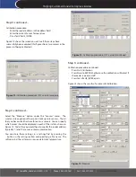
Enter the reader address in the address field

• 

Enter the current Sensor Temperature

• 

Press Test VALUE_INTER

• 

Figure 12 shows the screen you will see if these steps have 

successfully been executed (this figure shows two sensors in the 

process of being calibrated).

Figure 12: Calibration procedure (FCC version) continued

Step 3: 

continued...

Calibration procedure continued:

Press Start Calibration

• 

Press Store to EEPROM, otherwise the calibration will be lost if 

• 

the reader is powered off

Press Test VALUE_INTER again

• 

Figure 13 shows the results of a successful calibration.

Figure 13: Calibration procedure (FCC version) complete

Step 3: 

continued...

Select  the  “Measure”  option  under  the  “Sensors”  menu.    The 

wireless interrogation software can track up to 6 sensors.  The kit 

that you have will either have three or six sensors.  You can specify 

which sensor should be displayed in each of the six tiles shown in 

Figure 14.  To do this, you would have to specify the reader address 

(typically ‘1’) and the sensor -antenna combination.

You  can  store  these  settings  in  a  ‘settings  file’  by  pressing  the 

...  button  in  the  setting  section  and  specifying  a  file  name.   The 

software and the system are now ready to track temperature.

Figure 14: Measure

Summary of Contents for TempTrackr

Page 1: ...on Software Please contact SenGenuity if any item is either missing or damaged The wireless interrogation unit needs to be powered by a 5V 5 DC power supply All temperature sensors are interrogated by...

Page 2: ...ngenuity TempTrackr Start the Software from the Windows Start Menu or by double clicking the WSR T2 icon from the directory in which the software has been installed Figure 1 InstallShield Window for T...

Page 3: ...ued Connect the Wireless Interrogation Unit to a power supply 5V 5 DC 350mA as shown in Figure 6 You can now connect the RS232 RS485 cable to your PC laptop Step 2 Step 2 Setup and connect wireless in...

Page 4: ...t should be followed when locating the sensors The minimum distance between two sensors must be 4 inches 10 cm The minimum distance between any given sensor and the interrogation antenna must be 12 in...

Page 5: ...eaders Step 3 continued Select Calibrate from the Sensors Menu to obtain the Calibration Screen Sensors are identified by model numbers that reflect nominal the frequency of each sensor Since the six...

Page 6: ...ise the calibration will be lost if the reader is powered off Press Test VALUE_INTER again Figure 13 shows the results of a successful calibration Figure 13 Calibration procedure FCC version complete...

Page 7: ...nd found to comply with the limits for a Class B digital device pursuant to Part 15 of the FCC Rules These limits are designed to provide reasonable protection against harmful interference in a reside...

Page 8: ...pas l intensit n cessaire l tablissement d une communication satisfaisante Le pr sent metteur radio identifier le dispositif par son num ro de certification ou son num ro de mod le s il fait partie du...

Reviews: