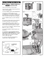

TEST INSTALLED FAUCET
1.
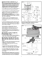
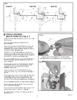
Setting the Detection Zone (Distance):
Fig. 1.
Detection Zone: 2" - 10" (50mm - 250mm)
Default: Set at Factory 6" (150mm)
Remove cover from ENCLOSURE. Disconnect GRAY
SENSOR WIRE
(1)
from circuit board, then reconnect.
Fig. 2.
2.
While the SENSOR CONTROL LED
(2)
is blinking
slowly, place your hand 1 - 2 in. (30-50mm) in front of
the sensor.
Fig. 2a.
3.
When the LED stops blinking and stays "ON", move
your hand to the desired position and hold in place until
the LED begins to blink again.
Fig. 2a.
4.
Once the SENSOR CONTROL LED
(2)
begins to
blink again, remove your hand from the detection zone.
When the flashing stops, the detection distance is set.
Fig. 2a.
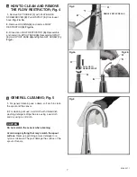
TO ENSURE A LAMINAR WATER FLOW
the air must
be slowly purged from the spout. To do so, cover the
SENSOR
(1)
while slowly opening the water supply
valves. When the water flows as a solid, smooth,
steady stream, uncover the SENSOR
(1)
and fully
open the water supply valve.
Fig. 1.
HOW TO CHANGE SENSOR
RANGE; (Factory set at 6") Fig. 2
1
Fig 1
Fig. 2a
1" - 2" (30mm - 50mm
BLINKING LED
UP TO 10" (250mm)
BLINKING
LED
2
2
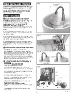
1.
Remove ENCLOSURE COVER.
2.
Close SUPPLY STOP
(5)
with 4mm Hex wrench.
Note: Keep water flowing out of faucet while shutting off.
3.
Pull off Red
(1)
and Black
(2)
CONNECTORS from
SOLENOID VALVE
(3)
.
4.
Unthread STRAINER
(4)
using a 7/16" socket.
5.
Pull out the STRAINER
(4)
and clean with an old
toothbrush. Rinse thoroughly with water.
6.
Install the STRAINER
(4)
back in its place and
tighten with a 7/16" socket.
Caution: do not over tighten strainer.
Note: It is recommended to clean strainer every 6
months.
7.
Replace ENCLOSURE COVER. Tighten cover
screws firmly.
HOW TO CLEAN FILTER; Fig. 3
CAUTION
Before opening ENCLOSURE
disconnect AC power supply.
DETECTION
ZONE
MAINTENANCE
When the Sensor detects a user, the water
immediately starts to flow. Water flow will stop Two
seconds after user is out of sensor range. The off delay
allows the user to comfortably move his hands without
the flow cycling on to off. As a precaution, a safety
timer will turn off the water, after the sensor has been
blocked for 59 seconds. The water will stay off until the
blockage is removed from the detection zone.
HAND WASH SENSOR OPERATION;
2
1
6
4
4
3
2
1
5
CLEAN
CLEAN
SCREENS
SCREENS
Fig.3
3
M 9 6 5 2 7 1
1
Fig. 2


