


16
leave the power source on to exploit the operating ventilator and re-
duce the time when it is not active.
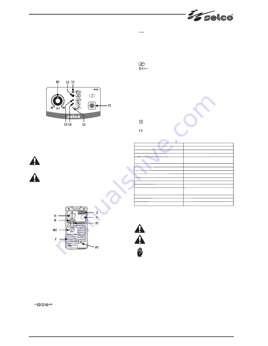
* P1: Potentiometer for setting the cutting current
Allows you to continuously adjust the cutting current. This current
stays unchanged during cutting when the supply and cutting condi-
tions vary within the allowed ranges.
* T1: gas test pushbutton.
Allows impurities to be removed from the compressed air circuit and
preliminary capacity and pressure settings to be made with no power
output.
Fig. 1
2.1.2 Rear control panel (Fig. 2)
* I1: Off/On switch
Turns on the electric power to the machine.
It has two positions, "
O
" off, and "
I
" on.
* When
I1
is in the on "
I
" position, the generator is operatio-
nal, but has voltage output only if
L2
is on.
* The machine is connected to the mains supply even if the
I1
switch is in the "
O
" position, and therefore there are
electrically live parts inside it. Carefully follow the instruc-
tions given in this manual.
* 1 : Supply cable.
* 2 : Ventilation slots. Never allow them to be obstructed.
* N : Serial number.
Fig. 2
3.0 TECHNICAL DATA
3.1 ldentification
The data plate stamped on the metal structure, see ch. 10.0 complies
with the IEC 974-1 and EN 60974-1 international standards and con-
tains the following information:
* Manufacturer's name and address.
* SELCO trademark
* ( Type ) Model
* ( N° ) Serial number
* ( ) The power source for plasma cutting comprises a
frequency converter followed by a transformer and rectifier that
transforms input voltage into direct current.
* (EN 60974-1, EN 50192) Safety standard applied.
* (OUTPUT) Output current and voltage ranges available.
* ( ---- ) Direct current.
* ( x ) Duty factor, that is, 10 minute time percentage during which
the welding can be carried out at a given current without any over-
heating.
* ( I2 ) Rated cut current.
* ( U2 ) Conventional load voltage.
* ( U0) Rated no-load voltage.
* Plasma cutting
* ( ) 1input phases.
* ( I.CL. H ) lnsulation class H.
* ( COOLING A. F. ) Forced ventilation cooling.
* ( IP 23 ) Casing protection degree in compliance with the EN 60529
Standard:
IP2X Casing protected against access to dangerous componente with
fingers and against the introduction of foreign matters with dia-
meter 12,5 mm.
IPX3 Casing protected against rain falling at 60° on the vertical line.
* ( U1 ) Rated power supply voltage.
* ( 50/60 Hz ) Power supply rated frequency.
* ( I1 ) Rated power supply current.
* ( ) Generator suitable for installation in places where major risks
of electric shocks are present.
* ( ) In compliance with the European regulations in force.
3.2 Technical characteristics
TECHNICAL CHARACTERISTICS
Power supply voltage
Delayed fuse
Rated power
Cutting current (x=60%)
(x=100%)
Cutting voltage (x=60%)
No-load voltage
Pilot arc current
Operating pressure
Flow rate
Protection class
Insulation class
Construction regulations
Dimensions (LXPXH)
Generator weight
Torch weight
GENESIS 30
1x230 V 50/60 Hz
16 A
3.35 Kw
30 A
25 A
92 V
340 V
15 A
5 bar
100 l/min
IP 23
H
EN 60974-1; EN 50199
EN 50078; EN 50192
130x360x250 mm
8.4 Kg
1.2 Kg
Above data are referred to environment al 40°C
4.0 TRANSPORT - UNLOADING
Never underestimate the weight of the equipment, see 3.0
(TECHNICAL DATA).
Never make the cargo pass or leave it suspended over
people or things.
Neither let the equipment or the single unit fall, nor put
it down with force.
Once it has been removed from the packing, the power source is sup-
plied with an extendible belt which can be used to move it in the hand
or on the shoulder.
5.0 INSTALLATION
5.1 GENERAL RULES
Choose an adequate installation area by following the criteria provided
in Section "1.0 WARNINGS-PRECAUTIONS-GENERAL ADVICE".
Do not position the power source and the equipment on surfaces with
inclination exceeding 15° with respect to the horizontal plane.
Protect the installation from heavy rain and sun. The machine protec-
tion degree (IP 23) is effective against water that falls down in a direc-
tion forming an angle up to 60° with the vertical line.


