


4
Shown for the SEL-751A with Ethernet, Fiber Optic, IRIG-B, EIA-232, 4 DO/3 DI/1 AO Option, 8 DI Option, and Voltage
Option. Refer to the SEL-751A manual for additional details and other options.
Wire sizes for connections are dictated by the terminal blocks and expected load currents. You may use the following table
as a guide in selecting wire sizes:
Connection Type
Minimum Wire Size
Maximum Wire Size
Grounding (Earthing) Connection
18 AWG (0.8 mm
2
)
14 AWG (2.5 mm
2
)
Current Connection
16 AWG (1.5 mm
2
)
12 AWG (4 mm
2
)
Potential (Voltage) Connection
18 AWG (0.8 mm
2
)
14 AWG (2.5 mm
2
)
Contact I/O
18 AWG (0.8 mm
2
)
14 AWG (2.5 mm
2
)
Other Connection
18 AWG (0.8 mm
2
)
14 AWG (2.5 mm
2
)
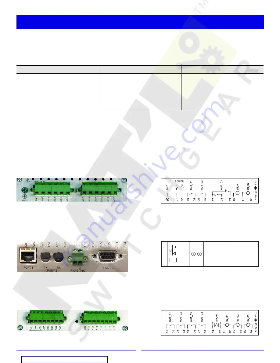
Card Slot A: Power Supply Card With 2 DI/3 DO
Step 1. Connect ground terminal
GND
to a rack frame or switchgear ground for proper safety and performance.
Step 2. Connect appropriate power supply to terminal 01 (
+/H
) and terminal 02 (
–/N
). Note that power terminals are
isolated from chassis ground.
Step 3. Connect up to 2 digital inputs, per application requirements, to optoisolated inputs IN101 (terminals 10 and 11)
and IN102 (terminals 11 and 12).
Step 4. Connect the 3 output contacts, per application requirements, to OUT101 (terminals 03 and 04), OUT102
(terminals 05 and 06), and OUT103 (terminals 07, 08, and 09).
Card Slot B: Main Board With Ethernet, Fiber Optic, IRIG-B, and EIA-232
Step 1. Connect communications devices as required to front DB-9 serial Port F (EIA-232), rear Port 3 (EIA-232),
10/100BASE-T Ethernet (RJ-45 connector) Port 1 and fiber-optic (ST
®
connector) serial Port 2.
Step 2. Connect IRIG-B time-code input to terminals 01 (+) and 02 (–).
Card Slot C: 3 Digital Inputs, 4 Digital Outputs, 1 Analog Output Card (3 DI/4 DO/1 AO)
Step 1. Connect additional digital inputs (IN_01, IN_02, IN_03) and outputs (OUT_01, OUT_02, OUT_03, OUT_04),
if required by application, using the connection diagram.
Step 2. Connect the analog (transducer) output AO_01 using terminals 09 and 10.
+5 V
dc
RX
D
+IR
IG
–B
TX
D
GND
5
–IR
IG
–B
RTS
GND
POR
T 3
E
IA
–232
IR
IG
–B
POR
T 2
F
IBER OPT
IC
TX
RX
1 2
4
3
6
8
CT
S
7
9
02
POR
T 1
ETHERNET
01
+
—
10
/10
0
B
A
S
E
–T
Connections


