


SEL-487B Data Sheet
Schweitzer Engineering Laboratories, Inc.
18
scrolling. Any message the relay generates because of an
alarm condition takes precedence over the rotating
display.
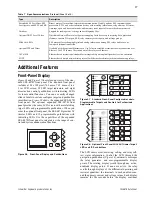
Status and Trip Target LEDs
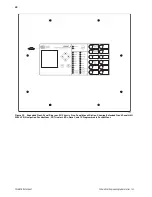
The SEL-487B standard front panel includes 16 pro-
grammable status and trip target LEDs as well as eight
programmable direct-action control pushbuttons on the
front panel. The optional SEL-487B expanded front
panel provides 24 programmable tricolor LED indicators
and 12 direct action control pushbuttons. These targets
are shown in Figure 27 and Figure 28 and explained in
Table 8.
Configurable Front-Panel Labels
Customize the SEL-487B front panel to fit your needs.
Use SEL
OGIC
control equations and slide-in configurable
front-panel labels to change the function and identifica-
tion of target LEDs, operator control pushbuttons, and
pushbutton LEDs. The blank slide-in label set is included
with the SEL-487B. Functions are simple to configure
using
AC
SEL
ERATOR
QuickSet.
You can use templates supplied with the relay or hand-
written on blank labels supplied with the relay to print
labels.
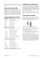
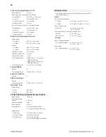
Control Inputs and Outputs
The basic SEL-487B (main board only) includes five
independent and two common inputs, and two standard
Form A, three high-current interrupting Form A, and
three Form C standard outputs, as in Figure 29.
Figure 29
Form A and Form C Output Contacts
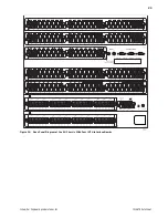
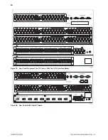
Add as many as four interface boards with the following
additional input/output (I/O) per interface board:
➤
six independent inputs
➤
eighteen common inputs (in two groups of nine)
➤
six high-speed, high-interrupting Form A outputs
➤
two standard Form A output contacts
The relay is available in either 9U or 7U chassis heights.
The 9U chassis supports as many as four INT4 interface
boards, while the 7U chassis option supports as many as
two INT4 interface boards. Assign the control inputs for
disconnect auxiliary contact status and breaker auxiliary
contact status. Set the input debounce time independently
for each input or as a group. You can use SEL
OGIC
control equations to program each control output.
Table 8
Description of Factory Default Target LEDs
Target LED
Function
87 (DIFF)
Differential element trip
BKR FAIL
Breaker failure protection trip
ZONE 1
Fault was in Zone 1
ZONE 2
Fault was in Zone 2
ZONE 3
Fault was in Zone 3
ZONE 4
Fault was in Zone 4
ZONE 5
Fault was in Zone 5
Standard Front-Panel LED Functions
ZONE 6
Fault was in Zone 6
50
Instantaneous overcurrent element trip
51
Time-overcurrent element trip
CT ALARM
Current transformer alarm
87 BLOCKED
Differential element blocked
TOS
Any terminal out of service
89 IN PROG
Disconnect operation in progress
89 ALARM
Disconnect failed to complete operation
PT ALARM
Potential transformer alarm
Expanded Front-Panel LED Functions
27
Phase Undervoltage
59
Phase Overvoltage
V01 ON
Phase Voltage V01 Present
V02 ON
Phase Voltage V02 Present
V03 ON
Phase Voltage V03 Present
BUS FAULT
Any Bus Zone Internal Fault
52 ALARM
Any System Breaker Failure Alarm
IRIG LOCK
IRIG Clock Input Lock
Form C
Form A