background image


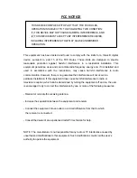
FCC NOTICE 


THIS DEVICE COMPLIES WITH PART 15 OF THE FCC RULES. 

OPERATION IS SUBJECT TO THE FOLLOWING TWO CONDITION: 

(1) THIS DEVICE MAY NOT CAUSE HARMFUL INTERFERENCE, AND 

(2) THIS DEVICE MUST ACCEPT ANY INTERFERENCE RECEIVED,   

INCLUDING INTERFERENCE THAT MAY CAUSE UNDERSIRED   

OPERATION.   


This equipment has been tested and found to comply with the limits for a Class B digital 

device, pursuant to part 15 of the FCC Rules. These limits are designed to provide 

reasonable protection against  harmful interference in a residential installation. This 

equipment generates, uses and can radiate radio frequency energy and, if not installed and 

used in accordance with the instructions, may  cause harmful interference to radio 

communication. However, there is no guarantee that interference will not occur in a   

particular installation. If this equipment does cause harmful interference to radio or   

television reception, which can be determined by turning the equipment off and on, the user   

is encouraged to try to correct the interference by one or more of the following measures :   


- Reorient or relocate the receiving antenna.   


- Increase the separation between the equipment and receiver.   


- Connect the equipment into an outlet on a circuit difference from that to which   

  the receiver is connected.   


- Consult the dealer of an experienced radio/TV technician for help.   


NOTE : The manufacturer is not responsible for any radio or TV interference caused by   

unauthorized modifications to this equipment. Such modifications could void the user’s   

authority to operate the equipment.   

Summary of Contents for SWR-220U

Page 1: ...Receiver MANUAL SWR 220U Sejin Electron Inc ...

Page 2: ...may cause harmful interference to radio communication However there is no guarantee that interference will not occur in a particular installation If this equipment does cause harmful interference to radio or television reception which can be determined by turning the equipment off and on the user is encouraged to try to correct the interference by one or more of the following measures Reorient or ...

Page 3: ...tings 5 2 1 User ID setting 5 2 1 1 User ID setting incase an EEPROM equipped on the receiver 5 2 1 2 User ID setting incase no EEPROM equipped on the receiver 7 3 Schematic diagram 8 3 1 Schematic diagram with 18 Pin DIP type package 8 3 2 Photo Module for different carrier frequencies 8 3 3 Language option jumper setting 9 ...

Page 4: ...liant device driver and HID device support Windows 98 Second Edition ME 2000 XP or lather version is recommended Note The Windows 98 Second Edition ME 2000 and Windows XP are registered trademark of Microsoft Corporation 3 One or more Application program for using consumer control buttons Without the application program only a few remote control buttons Keyboard and Mouse operation will work 1 3 E...

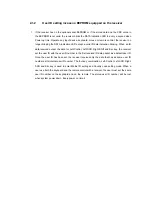
Page 5: ...as an optional serial EEPROM on the receiver board the receiver keeps user ID even though the system power down User ID setting procedure 1 Set the User ID 4 bit Dipswitch located under battery cover on the keyboard side after removing batteries To use both the keyboard and the remote control with single receiver the user must set the same user ID number for both on the keyboard and on the remote ...

Page 6: ...ift Right Shift and Esc key or move mouse Alternately aim the remote control to the IR lens of Receiver and press any button The four key combination Left Control Left Shift Right Shift and Esc key is used to enter Matrix ID setting and Country code setting mode 5 When a valid input detected the receiver stores the new user ID into the serial EEPROM Once the user ID setting is done the receiver au...

Page 7: ...for Left Control Left Shift Right Shift and Esc key the receiver set the user ID with the user ID number in the first received IR data packet as a default user ID Once the user ID has been set the receiver receives only the data that has as same user ID number as its internal user ID number The four key combination Left Control Left Shift Right Shift and Esc key is used to enter Matrix ID setting ...

Page 8: ...to the GND pin and the VCC pin of the photo module TBD 1 USB IR Receiver A 1 1 Wednesday August 29 2001 C 2001 Sejin Electron Inc C ORCADWIN CAPTURE DESIGN CYIR_RX DSN Title Size Document Number Rev Date Sheet of VCC VCC Caps Scrl Data RED Num Power Green GND VCC Shield D USB Cable D User ID Country Code Option Note for Photo Module TSOP1156 for 56KHz carrier frequency TSOP1138 for 38KHz carrier f...

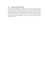
Page 9: ...escriptor table on chapter is always zero which indicates not localized The jumper JP2 must be ON for all non US language version keyboards except the keyboards that use US matrix sheet The jumper JP2 must be removed for the keyboards that use US matrix sheet which are currently US and Chinese language version When the optional serial EEPROM is equipped on the receiver the non US language option j...

Reviews: