background image


65

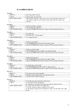
Error 29 

DISPLAY 

Cannot Control DVD Drive. 

CAUSE 

The DVD drive cannot be controlled. 

COUNTERMEASURE 

The DVD drive may be damaged. 


Error 31 

DISPLAY 

Storage Device Not Enough. 

CAUSE 

The program installer device does not have enough space. 

COUNTERMEASURE 

Send the LINDBERGH board in for repair with the keychip still in place. 


Error 32 

DISPLAY 

Installing Game Program Failed. 

CAUSE 

Transfer of the program failed. 

COUNTERMEASURE 

Check that the DVD drive is connected correctly. Check that the game disk is not 
scratched, damaged or dirty. 


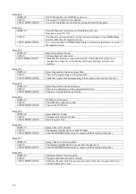
Error 33 

DISPLAY 

Storage Device is Not Acceptable. 

CAUSE 

The program installer device cannot be found. 

COUNTERMEASURE 

Send the LINDBERGH board in for repair with the keychip still in place. 


Error 34 

DISPLAY 

Storage Device Not Found. 

CAUSE 

The program installer device cannot be found. 

COUNTERMEASURE 

Send the LINDBERGH board in for repair with the keychip still in place. 


Error 35 

DISPLAY 

Storage Device is Not Acceptable. 

CAUSE 

The program installer device does not have enough space. 

COUNTERMEASURE 

Send the LINDBERGH board in for repair with the keychip still in place. 


Error 36 

DISPLAY 

Storage Device May be Broken. 

CAUSE 

The program installer device is broken. 

COUNTERMEASURE 

Send the LINDBERGH board in for repair with the keychip still in place. 


Error 37 

DISPLAY 

Verifying Game Program Failed. 

CAUSE 

The program image is unverified due to the program image not existing on the 
game disk or server. 

COUNTERMEASURE 

Check that the correct game disk is inserted. 


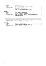
Error 41 

DISPLAY 

Server Not Respond. 

CAUSE 

The server is not responding. 

COUNTERMEASURE 

Check the network settings. 
Set IP Address and other settings. 
Check that the network cable has not been pulled out. 


Error 42 

DISPLAY 

Server Mount Failed 

CAUSE 

The server directory is could not be reached. 

COUNTERMEASURE 

Check the network settings. 
Set IP Address and other settings. 
Check that the network cable has not been pulled out. 

Summary of Contents for MINI DELUXE THE HOUSE OF THE DEAD 4

Page 1: ...read this MANUAL carefully to understand the contents stated herein After reading this MANUAL be sure to keep it available nearby the product or somewhere convenient in order to be able to refer to it...

Page 2: ...0 2 2 VTS CREDIT BOARD OPTION SETTINGS 69 10 2 3 PRICE OF PLAY SETTINGS UK 70 10 2 4 PRICE OF PLAY SETTINGS EURO 71 11 CONTROLLER UNIT GUN 72 12 REPLACEMENT OF FLOURESCENT LAMPS 78 13 PERIODIC INSPECT...

Page 3: ...uct Indicates that mishandling the product by disregarding this will cause a potentially hazardous situation which may not result in personal injury but could damage the product Be sure to turn off th...

Page 4: ...t to change without prior notification The contents described herein are fully prepared with due care However should any question arise or errors be found please contact SEGA 1 1 INSPECTIONS IMMEDIATE...

Page 5: ...will the correct parts be identified SEGA product has warning displays on stickers labels or printed instructions adhered attached to or incorporated in the places where hazardous situations can arise...

Page 6: ...ols spare parts etc as regards HOUSE OF THE DEAD 4 MINI DELUXE a new SEGA product This manual is intended for those who have knowledge of electricity and technical expertise especially in IC s CRT s m...

Page 7: ...transformer input tapping For more information see the section in this manual dealing with changing the transformer voltage Please note that the input voltage of the machine has been set during manufa...

Page 8: ...6 4 NAME OF PARTS Width cm Depth cm Height cm Weight kg When Assembled 76 5 140 5 197 5 Approx 180...

Page 9: ...ION OF CONFORMITY 3 HDF 1056UK 1 DECAL BUTTON PLATE HDF MDX MULTI 4 540 0043 91 1 L WRENCH FOR HEX SOC 3MM 20 601 11691 1 CARTON BOX LBG 401 0S1019 2 SELF SEAL BAG 402 420 6908 03UK 1 SERVICE MANUAL H...

Page 10: ...ual Since this is a complex machine erroneous assembling can cause an electric shock or damage to the machine resulting in not functioning as per performance When carrying out the assembly work follow...

Page 11: ...or directly make adjustments in a manner so that the castors will be raised approximately 5mm from the floor and make sure that the machine position is level 1 Install the machine in a suitable locati...

Page 12: ...door 3 Disconnect Wire Harness Transformer In HDF 66016UK from the 6 way Mate n Lok connector on the transformer primary 4 Using Amp extraction tool No 458994 1 or 876047 1 not supplied extract the pi...

Page 13: ...owing information is displayed on this screen NODE The currently displayed NODE number and the total number of nodes NAME ID Code CMD VER Command format version JVS VER JVS standard version COM VER Co...

Page 14: ...k the output of the monitor Enter MONITOR TEST and the following color bars will be displayed Press the TEST Button and the screen will change to the following crosshatch screen Press the TEST Button...

Page 15: ...nted at the screen and the values to the right of GUN X and GUN Y move between 00 to FF START The player START Buttons GUN TRIGGER The trigger on the gun GUN BUTTON The Button on the gun GUN SPEED X T...

Page 16: ...ettings Perform the tests as follows START1 LAMP Select START1 LAMP and press the TEST Button to turn the option ON The player 1 START Button will light up The lamp will remain on for as long as the T...

Page 17: ...YER2 GUN ADJUSTMENT Select PLAYER1 GUN ADJUSTMENT on the Gun Calibration Setting screen and press the TEST Button NOTE PLEASE SHOOT GRID WITH PLAYER1 GUN on the screen will flash Follow the on screen...

Page 18: ...t the mark to the lower right The mark to the lower right will disappear and the same mark will be displayed in the center Press the TEST Button to return to the Gun Calibration Setting screen Aim and...

Page 19: ...ts will not be saved and you will return to the Gun Calibration Setting screen OUT OF SCREEN is displayed when the gun cross is perceived to be out of screen Refer to the following procedure when adju...

Page 20: ...ion so that casters do not tread power cords and earth wires Damaging the power cords can cause an electric shock and or short circuit When moving the machine do not push the cabinet from the left rig...

Page 21: ...TENTION TO CUSTOMERS To avoid injury and trouble be sure to constantly give careful attention to the behaviour and manner of the visitors and players To avoid electric shock and short circuit do not a...

Page 22: ...status Then identify the cause of the fault on the item which caused the over current fix The colour image on The screen is incorrect Incorrect monitor adjustment Make appropriate adjustments Refer to...

Page 23: ...turned on Demo movies and game rankings are displayed on the screen Audio may also be played from speakers on the left and right sides of the main cabinet However it is possible to select whether sou...

Page 24: ...ay and by the coin meter A player plays on the left Player 1 or the right Player 2 by pressing the START button on that side Pressing the START button begins the game When the game starts a demo plays...

Page 25: ...upon clearing a stage the player will automatically start the next stage with 3 grenades 1 RELOAD Shake the gun controller to reload Release the trigger when reloading 2 GRENADE Press this button to t...

Page 26: ...l shake the enemy off 3 Being grabbed by an enemy 4 The gun cannot be fired and grenades cannot be used when grabbing an enemy A player can join a game in progress at any time by inserting coins and p...

Page 27: ...d during the game Medical Kit Increases life by one Gold Coin Increases a player s score Silk Hat Increases a player s score Mini Magician Increases a player s score Golden Frog Increases a player s s...

Page 28: ...ncrease remaining lives Also upon clearing a stage your performance may award extra lives Repeated play and knowledge of the levels will aid in gathering extra lives Use grenades effectively As well a...

Page 29: ...e MEMORY TEST mode check all of the IC s on the IC BD Monthly MEMORY On the TEST MENU screen choosing the MEMORY TEST allows self test to be performed In this test RAM ROM are tested Monthly PERIODIC...

Page 30: ...ed to enter TEST mode Also has function during TEST mode Refer to the later section detailing TEST mode SERVICE BUTTON SERVICE SW Gives credits without registering on the coin counter Also used during...

Page 31: ...the SYSTEM TEST MENU Be careful because if the power is turned off before that point changes to the settings will be lost Use with the specified settings If settings other than those specified are use...

Page 32: ...rsion REGION The region setting MEMORY SIZE The onboard memory size STORAGE DEVICE The total capacity of the program installer device STORAGE MODEL Displayed in the above photo but not actually displa...

Page 33: ...re complete a now checking screen will be displayed and uninstall cannot be performed If the program installer device does not contain any game data the game information will be displayed in grey and...

Page 34: ...ODEs NAME ID Code CMD VER Command format version JVS VER JVS standard version COM VER Communication version SWITCH Number of players and number of 1P switches COIN Number of coin slots ANALOG Number o...

Page 35: ...time The following information is displayed on this screen SYSTEM System switch input data PLAYER Player number and player switch input data COIN Slot number and coin input data ANALOG Channel number...

Page 36: ...ck the output of the monitor Enter MONITOR TEST and the following color bars will be displayed Press the TEST Button and the screen will change to the following crosshatch screen Press the TEST Button...

Page 37: ...ill be emitted from that speaker It is possible to set multiple speakers to emit the test sound at the same time If the stipulated sound card is not present this test screen will not display this menu...

Page 38: ...4 g 5 g 6 The following information is displayed on this screen g 1 COIN CHUTE TYPE COMMON Allow all credits to be used by all players INDIVIDUAL Treat each player s credits individually g 2 SERVICE T...

Page 39: ...gs that cannot be performed on the Coin Setting screen to be performed The following information is displayed on this screen COIN CHUTE 1 MULTIPLIER Coin conversion rate for 1 How many coins 1 inserte...

Page 40: ...e enough credits to play the game A total of 8 game costs can be defined The game cost is defined by the BOOT ID and when the second boot recognizes the game the game cost defined by the BOOT ID will...

Page 41: ...rsor to the category that you wish to change and press the TEST Button to increase that value Holding the TEST Button down will make the value continuously increase Changes will come into effect when...

Page 42: ...ust use the following factory settings NETWORK TYPE MAIN MAIN NETWORK No need to set The following information is displayed on this screen NETWORK TYPE Sets the type of network to use MAIN NETWORK Set...

Page 43: ...ot contain instructions for performing network settings or tests NETWORK SETTING Screen NETWORK TEST Screen j GAME TEST MODE Opens the Game Test Mode allowing game specific settings and tests to be pe...

Page 44: ...ow a INPUT TEST Tests each input device used in the game b OUTPUT TEST Tests each output device used in the game c GAME ASSIGNMENTS Adjusts game settings d GUN CALIBRATION SETTING Performs sight setti...

Page 45: ...nted at the screen and the values to the right of GUN X and GUN Y move between 00 to FF START The player START Buttons GUN TRIGGER The trigger on the gun GUN BUTTON The Button on the gun GUN SPEED X T...

Page 46: ...utton to enter the selected item s test For Overseas Other than Europe Perform the tests as follows START1 LAMP Select START1 LAMP and press the TEST Button to turn the option ON The player 1 START Bu...

Page 47: ...he lamp will remain on for as long as the TEST Button is held down START2 LAMP Select START2LAMP and press the TEST Button to turn the option ON The player 2 START Button will light up The lamp will r...

Page 48: ...he game with Can be set between 1 and 9 However cannot be set higher than the MAX LIFE setting LIFE SETTING MAX LIFE The maximum number of lives a player may have Can be set between 1 and 9 BLOOD COLO...

Page 49: ...the Player 1 side d 3 PLAYER1 GUN DEFAULT ADJUSTMENT Adjust the default sight settings for the Player 1 side d 2 PLAYER2 GUN ADJUSTMENT Adjust the sight for the Player 2 side Operated in the same way...

Page 50: ...is pointed at the screen 1P is red 2P Gun Cross This is displayed when the gun is pointed at the screen 2P is blue OUT OF SCREEN is displayed when the gun cross is perceived to be out of screen Pointi...

Page 51: ...AYER2 GUN ADJUSTMENT Select PLAYER1 GUN ADJUSTMENT on the Gun Calibration Setting screen and press the TEST Button NOTE PLEASE SHOOT GRID WITH PLAYER1 GUN on the screen will flash Follow the on screen...

Page 52: ...t the mark to the lower right The mark to the lower right will disappear and the same mark will be displayed in the center Press the TEST Button to return to the Gun Calibration Setting screen Aim and...

Page 53: ...ERVICE Button The calibration results will not be saved and you will return to the Gun Calibration Setting screen OUT OF SCREEN is displayed when the gun cross is perceived to be out of screen Refer t...

Page 54: ...libration Setting screen and press the TEST Button Press the TEST Button to set the Control Unit Gun targeting to the pre set default values When setting is complete the message COMPLETED will appear...

Page 55: ...ECK Checks the registered speed when the guns are shaken Player 1 and Player 2 Guns are both checked together e 2 PLAYER1 GUN SPEED ADJUSTMENT Adjusts the registered speed for when the Player 1 gun is...

Page 56: ...screen Moving the gun for each player will alter the values displayed on the X axis and Y axis speed bars Use this screen to check that the current maximum speed setting matches the speed values by m...

Page 57: ...UN SPEED SETTINGS again Adjusts the registered speed for when the Player 1 gun is shaken This is the same for PLAYER2 GUN SPEED ADJUSTMENT Select PLAYER1 GUN SPEED ADJUSTMENT on the Gun Speed Setting...

Page 58: ...G will be displayed on the screen and it will then proceed automatically to the next screen The set MAX speed values will be displayed Move the gun again and check that these are no problems with thes...

Page 59: ...57 PLAYER1 GUN SPEED ADJUSTMENT COMPLETED Press the TEST Button and the message COMPLETED will be displayed on the screen and it will then proceed automatically to the Gun Speed Setting screen...

Page 60: ...N SPEED DEFAULT ADJUSTMENT on the Gun Speed Setting screen and press the TEST Button to display the following screen Press the TEST Button to set the Control Unit Gun speed settings to the pre set def...

Page 61: ...Slot 1 COIN 2 The number of coins inserted into Coin Slot 2 TOTAL COINS The total number of coins inserted into the coin slots COIN CREDITS The number of credits for the coins inserted SERVICE CREDIT...

Page 62: ...of continues used by 1P and 2P TOTAL TIME The amount of time the unit has been in operation PLAY TIME The amount of time the game has been played AVERAGE PLAY TIME The average play time for one game L...

Page 63: ...nutes are included in the item OVER 10M00S Press the TEST Button after viewing You will return to the Game Test Mode screen GAME HISTOGRAM 0M 00S 0M 29S 0 0M 30S 0M 59S 0 1M 00S 1M 29S 0 1M 30S 1M 59S...

Page 64: ...core To clear data use the SERVICE Button to move the cursor to YES CLEAR and then press the TEST Button When the data has been cleared the message COMPLETED will be displayed and the screen will retu...

Page 65: ...hics card cannot be found COUNTERMEASURE Send the LINDBERGH board in for repair with the keychip still in place Error 08 DISPLAY Sound Card Not Found CAUSE The LINDBERGH board s sound card cannot be f...

Page 66: ...disk COUNTERMEASURE Check that a game disk corresponding to the keychip is inserted into the drive Error 22 DISPLAY Game Program Not Found on Device CAUSE There is no game image on the game installer...

Page 67: ...in for repair with the keychip still in place Error 35 DISPLAY Storage Device is Not Acceptable CAUSE The program installer device does not have enough space COUNTERMEASURE Send the LINDBERGH board in...

Page 68: ...am image on the network server COUNTERMEASURE Check that the game title place on the network server and the keychip correspond to each other Caution 51 DISPLAY Wrong Resolution Setting CAUSE The game...

Page 69: ...thin the Coin Chute Tower The Klingon2 board is connected to the coin validator and lamps via a dedicated wiring harness depending upon the coin validator used Wiring Harness Validator LM1006 Coin Con...

Page 70: ...ndicated by the illustration above All Credit settings are configured via the DIP switches also located on the VTS Board please refer to later on in this manual for the appropriate switch settings IMP...

Page 71: ...OFF ON OFF ON 500Pta 200Pta 100Pta 50Pta 25Pta 200Pt old 50Pta old 25Pta old Spain SR3 NRI Parallel ON ON OFF ON 500Pta 200Pta 100Pta 50Pta 25Pta 200Pta 50Pta old 25Pta old Spain Coin Controls C220 Pa...

Page 72: ...onus OFF ON OFF ON OFF 12 50p 3 1 6 2 ON ON OFF ON OFF 13 50p 2 1 5 2 OFF OFF ON ON OFF 14 60p No Bonus ON OFF ON ON OFF 15 60p 2 1 4 2 OFF ON ON ON OFF 16 80p No Bonus ON ON ON ON OFF 17 80p 1 25 1 2...

Page 73: ...OFF ON OFF ON OFF 12 50 3 1 6 2 ON ON OFF ON OFF 13 50 2 1 5 2 OFF OFF ON ON OFF 14 60 No Bonus ON OFF ON ON OFF 15 60 2 1 4 2 OFF ON ON ON OFF 16 80 No Bonus ON ON ON ON OFF 17 80 1 25 1 2 1 50 2 5...

Page 74: ...72 11 CONTROLLER UNIT GUN...

Page 75: ...likely broken Use the following instructions to take the gun apart and replace the broken part The exterior casing comprised of cover L and cover R must be opened up in order to change interior parts...

Page 76: ...74...

Page 77: ...75...

Page 78: ...76...

Page 79: ...77...

Page 80: ...en replacing them BILLBOARD LAMP REPLACEMENT 1 Take off screws and remove the Upper and Lower Billboard Sash 2 Pull out the Billboard from the cabinet to replace the Fluorescent 3 Reassemble in revers...

Page 81: ...nt to remove the ASSY CONTROL PANEL Locate the ASSY SWITCH with the defective lamp and twist to remove Pull the bulb from the lamp housing and replace by push to fit This product uses a LED lamp The B...

Page 82: ...Monthly Setting check INTERIOR Cleaning Annually POWER PLUG Inspection and cleaning Cabinet surface Cleaning As occasion arises CAUTION TO BE HEEDED WHEN CLEANING THE CRT SURFACE Static preventive co...

Page 83: ...e fuse is blown due to instantaneous overload Firmly insert the plug into the outlet Make sure that the power supply voltage are correct Remove the cause of overload to reset the circuit protector Aft...

Page 84: ...e control Perform SOUND TEST Check connector connection from IC BD to Speaker During game play Controller sighting is irregular GUN alignment is incorrect GUN SENSE BD malfunctioning ASSY MASK malfunc...

Page 85: ...roper connection may cause electric shock short circuit or fire When connecting the connectors be sure to attach them correctly There is only one correct way in which they must be connected Attempting...

Page 86: ...Turn the Main SW off d Remove the Side Door from the left hand side of the cabinet by using the Master Key and taking off the 2 screws e Remove all the associated harnesses then remove the 4 screws r...

Page 87: ...ith the packaging material and put it in the original transit box as shown Putting it upside down or packing otherwise in the manner not shown can damage the GAME BOARD and parts 15 3 COMPOSITION OF G...

Page 88: ...rt Number Description 401 HDF 1072 CUK STICKER SIDE L 02 403 HDF 1072 EUK STICKER SIDE R 02 20 HDF 1502 BUK STICKER SIDE L 01 21 HDF 1502 DUK STICKER SIDE R 01 22 HDF 1513 AUK STICKER SIDE DOOR L 23 H...

Page 89: ...2 16 PK0382 COVER SHRINK MDX 1 17 PK0383 PALLET HDF MDX 1 19 440 WS0070 EG STICKER W PUSH GBN SD 1 21 LB1102 STICKER DANGEROUS VOLTAGE ON SIDE DOORS BACK 3 22 LB1104 STICKER CAUTION HOT SURFACE LIGHT...

Page 90: ...DF 1500UK ASSY CABINET LOWER 1 3 HDF 1540UK ASSY CNTRL PNL 1 4 HDF 1095UK ASSY LIGHT BOX 2 9 PP1087 BOX CASH FOR MINI DOOR 1 201 000 T00525 0B M5X25 MSCR TH BLK 3 8 8 202 000 P00616 W M6X16 MSCR PAN W...

Page 91: ...ASSY POWER BASE 1 7 HDF 4600UK ASSY ELEC RIGHT 1 9 HDF 1506UK JOINT BASE 1 10 HDF 1004UK CONTROLLER CABLE BRKT 2 11 HOD 1530UK ASSY FAN UNIT UK 1 12 HDF 1504UK LEFT HOLSTER 1 13 HDF 1505UK RIGHT HOLS...

Page 92: ...SCR PAN W FS PAS 4 2 7 2 4 205 000 P00416 W M4X16 MSCR PAN W FS PAS 5 1 2 215 030 000840 SB M8X40 BLT W S BLK 3 4 9 6 14 216 068 852216 0B M8 WSHR 22OD FLT BLK 3 4 9 6 12 1 13 1 14 217 032 000530 M5X3...

Page 93: ...N HOT SURFACE LIGHT BOX 1 201 000 T00435 0B M4X35 MSCR TH BLK 2 2 2 202 300055M M6X30 COACH CSK BLT 3 8 8 203 050 F00600 M6 NUT FLG SER PAS 3 8 8 204 030 000830 S M8X30 BLT W S PAS 4 2 OUTER ONLY 2 20...

Page 94: ...92 17 5 ASSY MONITOR UK HDF 1070UK...

Page 95: ...80 A02064 WX ROUTER TWIST D20 SO6 4 WOOD X 8 202 000 T00420 0B M4X20 MSCR TH BLK 2 3 5 2 5 203 000 T00425 0B M4X25 MSCR TH BLK 4 6 18 4 10 207 050 F00600 M6 NUT FLG SER PAS 101 4 4 208 068 652516 M6 W...

Page 96: ...U00300 M3 NUT NYLOK PAS 10 202 068 330808 PN M3 WSHR 8OD FLT NYLON 10 17 7 ASSY AC UNIT HDF 1530UK Seq No Component Part Description Component Reference Number off 1 HDF 1531UK AC BRKT 1 3 LB1096 STIC...

Page 97: ...102 MA1019 CASTOR 75 2 201 030 000620 S M6X20 BLT W S PAS 102 16 16 202 060 F00600 M6 WSHR FORM A FLT PAS 102 16 16 17 9 ASSY FAN UNIT UK HDF 1530UK Seq No Component Part Description Component Referen...

Page 98: ...T00420 0B M4X20 MSCR TH BLK 3 4 4 301 HDF 66024UK WH START SW NOT SHOWN 1 17 11 ASSY LIGHT BOX HDF 1095UK Seq No Component Part Description Component Reference Number off 1 HDF 1096UK LIGHT TRAY 1 2 H...

Page 99: ...X ROUTER TWIST D12 SO6 4 WOOD X 3 105 280 A02064 WX ROUTER TWIST D20 SO6 4 WOOD X 5 106 RND 838 001 FUSE BOARD NOT SHOWN 1 107 OS1011 PCB FEET RICHCO LCBS L 5 01 106 4 4 201 000 P00516 W M5X16 MSCR PA...

Page 100: ...0 A02064 WX ROUTER TWIST D20 SO6 4 WOOD X NOT SHOWN 5 201 000 P00416 W M4X16 MSCR PAN W FS PAS 2 4 4 202 012 P00325 N4X1 S TAP PAN PAS 101 4 102 4 8 301 HDF 66005UK WH AUDIO A NOT SHOWN 1 302 HDF 6600...

Page 101: ...HDF 66002UK WH DC PWR 1 303 HDF 66003UK WH SPKR A 1 304 HDF 66004UK WH VOL EXT A 1 305 HDF 66006UK WH AMP PWR 1 306 HDF 66011UK WH AUDIO B 1 17 15 ASSY INSTALLATION KIT MDX HDF INST MDX Seq No Compon...

Page 102: ...ide numeral of the code is 0 then the wire will be of a single colour shown by the left hand side numeral see the list above Note 1 If the right hand side alphanumeric is not 0 that particular wire ha...

Page 103: ...101 19 APPENDIX A ELECTRICAL SCHEMATIC The following page contains the electrical schematic for this machine...

Page 104: ......

Page 105: ......

Page 106: ......

Page 107: ...SEGA AMUSEMENTS EUROPE Suite 3a Oak House 12 22 West Street Epsom Surrey United Kingdom KT18 7RG Telephone 44 0 1372 731 820 Fax 44 0 1372 731 849 SEGA 2006...
Reviews: