background image

Release Version 2.0 


3.


Product Parts and Peripheral Device Connection 

3-1. Front Interface 


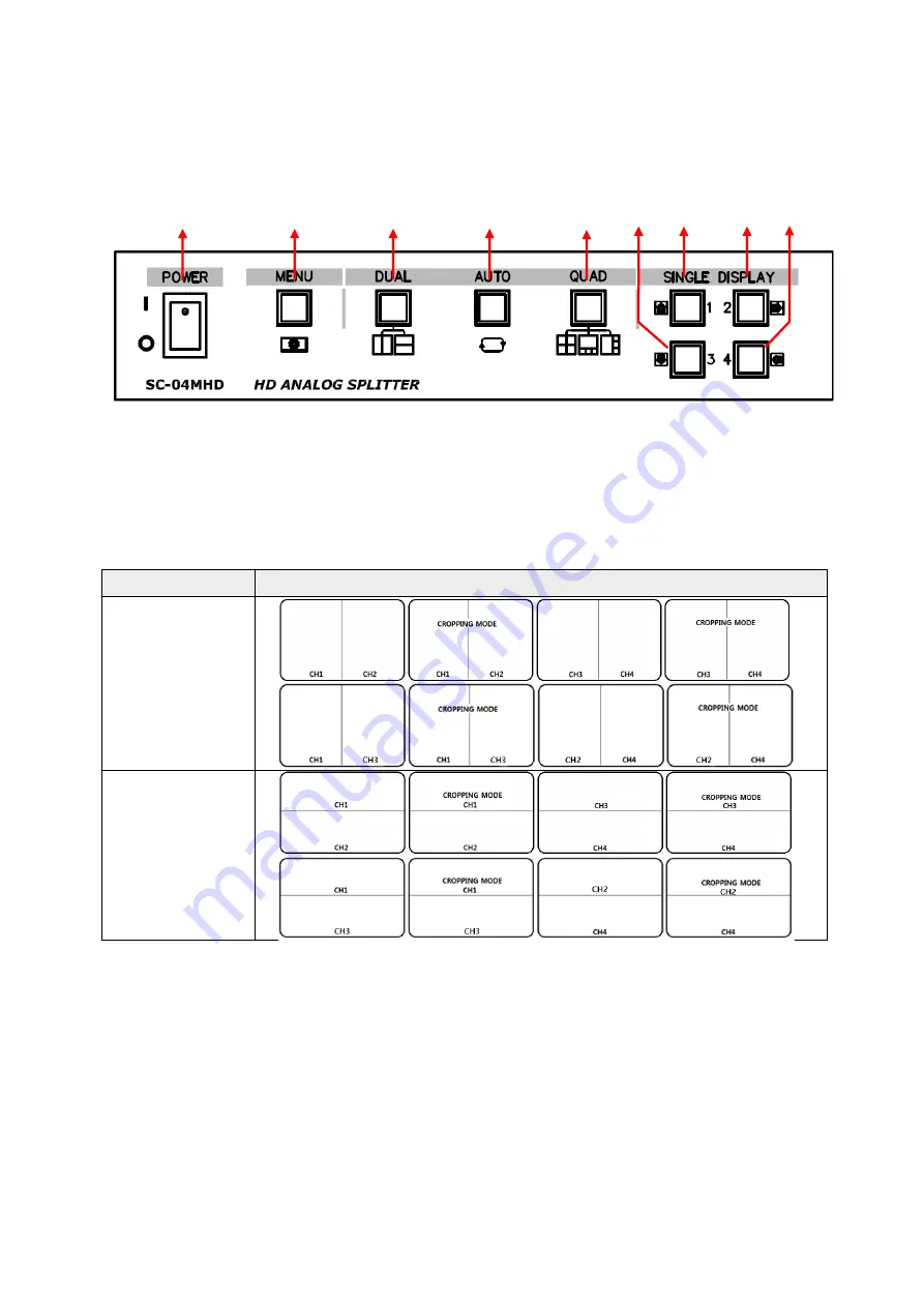
①  POWER:

 To turn the power on/off. 

②  MENU

: To set up this item and/or check the current settings. 

③  DUAL: 

To turn to the horizontal/vertical 2-split screen mode. 

                    The green LED will be on when pressing this button in split mode. 
                    In the menu, it is possible to enter the sub-menu or save the settings via this button. 

Split Mode 

Split Screen 

Vertical 2-split 

mode 


Horizontal 2-split 

mode 


  ②   


  ③     


  ④   


          ⑤


⑧      ⑥


  ⑦      ⑨ 


Summary of Contents for SC-04MHD

Page 1: ...Release Version 2 0 4CHANNEL VIDEO INPUT DIGITAL SPLITTER SC 04MHD User s Manual ...

Page 2: ...cord section or unplug the power plug with wet hands If the power cord is loose do not plug in There may be a risk of fire and electric shock Keep the device in a cool place where doesn t let direct sunlight Keep it at a proper temperature and avoid heating appliances like candle or heater Also keep the equipment or tools away from places where people come and go It may cause fire Pay attention to...

Page 3: ...m and secure the cover of the main body It may be the cause of failure by environmental factors Refer the device to the service center and get regular checkup to maintain the performance of the system We are not responsible for any damages caused by user s carelessness Make sure to plug the power cord with grounded outlet There is a risk of electrical shock and personal injury Place the power plug...

Page 4: ... 2 Features Various video input AHD TVI CVI CVBS Support Loop through output Display video of four cameras in real time Various split mode 2 split 4 split or 3 split screen Auto sequence function RS 485 communication port for a remote control Alarm port 4 Input 1 Output Relay Contact Display and save the date and time when alarm and loss are generated Various video output resolution HDMI 1920x1080...

Page 5: ...set up this item and or check the current settings DUAL To turn to the horizontal vertical 2 split screen mode The green LED will be on when pressing this button in split mode In the menu it is possible to enter the sub menu or save the settings via this button Split Mode Split Screen Vertical 2 split mode Horizontal 2 split mode ...

Page 6: ...the split mode Split Mode Split Screen Vertical 4 split mode Horizontal 4 split mode Vertical 3 split mode SINGLE DISPLAY 1 To display the channel 1 in full screen and select a channel to crop in general To move to the top in the menu mode SINGLE DISPLAY 2 To display the channel 2 in full screen and shift the cropped image in general To move to the right in the menu mode SINGLE DISPLAY 3 To displa...

Page 7: ...appear and the AUTO KEY LED off 2 Horizontal 2 Split Press the AUTO KEY for a few seconds to make the AUTO KEY LED flicker and a red line is displayed Press the SINGLE DISPLAY 3 to select the image at the bottom and press SINGLE DISPLAY 1 to shift the red line to select the image at the top Press the SINGLE DISPLAY 2 to shift image to the bottom and press the SINGLE DISPLAY 4 to shift the image to...

Page 8: ...splayed Input OFF mode 0 Input ON mode 1 The GND and the Inx produce a short circuit The relevant video channel will not be displayed when the alarm signal is entered into a channel having signal attenuation Alarm Input The GND and the Inx open or produce a short circuit by using a contact signal switch relay that does not receive electric signal When an alarm is produced by a foreign alarm input ...

Page 9: ... 0x34 CH 01 Full Display UP Cropping Channel Selection Left up Screen Screen Menu 0xA0 0x16 0x01 0x34 0x4b 0x35 CH 02 Full Display RIGHT Cropping Channel Position Shift to the right up Screen Menu 0xA0 0x16 0x01 0x35 0x4c 0x36 CH 03 Full Display DOWN Cropping Channel Selection Right down Screen Screen Menu 0xA0 0x16 0x01 0x36 0x4d 0x37 CH 04 Full Display LEFT Cropping Channel Position Shirt to the...

Page 10: ...ch as a DVR after connecting it to the BNC port the displayed image may blur due to the termination problem HDMI HDMI output MINI USB To update the firmware GND Ground Alarm input and power output To control the product by an external device RELAY Electric signal output To operate a light or an emergency bell by using electric signal when any alarm occurs N O Normal Open the contact point is off N...

Page 11: ...E DATE FORMAT LOCATION DATE SET TIME SET CH01 CH02 CH03 CH04 NO YY MM DD HH NN SS EVT CH 4 1 Start up Screen of the Menu Press the menu button on the front side of SC 04MHD to display the menu as shown above Move the sub menus by using the buttons and press the DUAL Select button to select one of the sub menus To enter the setup screen please press the menu button when the above image is displayed...

Page 12: ...istance by RS 485 The available rates are 2400 4800 9600 19200 SYSTEM SET Press buttons to select BAUDRATE Press buttons to set the baud rate among 2400 4800 9600 19200 4 2 3 ALARM I O Set the alarm input output SYSTEM SET Press buttons to select ALARM I O Press buttons to set the ALARM I O ON OFF When this function is off the alarm does not operate 4 2 4 ALARM HOLD Set the alarm screen duration t...

Page 13: ...ion SYSTEM SET Press the buttons to select the LOSS Press the buttons to set the LOSS ON OFF When this function is off it does not detect any video signal loss 4 2 8 EVENT SAVE Save the warned channel and occurred time to the EVENT LIST when an alarm or video loss alert occurs SYSTEM SET Press the buttons to select the EVENT SAVE Press the buttons to turn this function ON OFF When this function is...

Page 14: ...mera control or images appearing intermittently In an environment installed as below picture UTC CONTROL should be ON in order to control camera from DVR 4 2 11 DEFAULT ALL Reset it to the factory default settings SYSTEM SET Press the buttons to select the DEFAULT ALL Press the buttons to turn this function ON OFF To reset it to the factory defaults please turn this function on and press the DUAL ...

Page 15: ...his video input format same as the actual input signal format When output of MATRIX SWITCHER is connected to input of SC 04MHD INPUT SET should be fixed to CVBS NTSC or CVBS PAL and LOSS OFF in SYSTEM setting When switching cameras in MATRIX SWITCHER a black image may be shown on the output screen of SC 04MHD and camera images may darkened and lightened up 4 4 OUTPUT SET Set the output signal reso...

Page 16: ...lution Supported Resolution 1920x1080p 25 30 50 60 1920x1080i 50 60 1360x768 60 1600x1200 60 1024x768 60 1280x720 50 60 4 4 2 CVBS Set the NTSC PAL video format Press the buttons to select CVBS Press the buttons to set the CVBS format NTSC or PAL To complete this setting please press the DUAL Select button 4 5 DISPLAY SET 4 5 1 CH INFO BOX Display the video input status on the left top of the moni...

Page 17: ...ons to select the DATE TIME Press the buttons to set it ON OFF 4 5 6 BORDER LINE Select whether to have the border line to distinguish the split video images easily DISPLAY SET Press the buttons to select the BORDER Press the buttons to turn this function ON OFF 4 5 7 SEQUENCE TIME Set the display switching time by seconds 3 99 seconds in the Auto Sequence mode SYSTEM SET Press the buttons to sele...

Page 18: ...buttons to select the VIDEO SCALE Press buttons to set the video screen ratio 4 6 DATE TIME SET 4 6 1 DATE FORMAT Set the date format DATE TIME SET Press the buttons to select the DATE FORMAT Press the to set the date format 4 6 2 LOCATION Set the location to display the date and time on the screen DATE TIME SET Press the buttons to the LOCATION Press the buttons to move the displayed date and tim...

Page 19: ... settings CH TILTE SET Press the buttons to select the channel to be modified Press the DUAL SELECT button to enter the channel settings 4 7 2 TITLE Change the channel title name Up to 16 letters Move to each letter total 47 letters by using and buttons and press the DUAL SELECT button to enter the selected letter After entering the channel title please press the AUTO PREV or ESC buttons to save t...

Page 20: ...ss occurs in a specific channel S_L Signal Loss ALM Alarm 5 Connection Diagram AHD TVI and CVI cameras do not have standardized signal format so depending on the manufacturer images may not be output properly and UTC control may not work properly Do not connect the cable to the port when Loop Output is not used ...

Page 21: ...s to the supported input video resolutions of SC 04MHD Please check if the input video format and video format setting of SC 04MHD are same Please check the connection status of the BNC connectors of input video Please check if the monitor input is set as HDMI Please check if the HDMI output resolution matches the monitor s input resolution The connected cable length should not exceed the recommen...

Page 22: ...HFBT RG 6 600m based on 5C HFBT 200m 10Ω Loop through Output 3C 2V 100m based on 3C 2V 200m 20Ω CVBS Output 3C 2V 200m based on 3C 2V 200m 20Ω HDMI Output HDMI Cable 3m VGA Output RGB Cable 1m Input Power Power Consumption MAX DC 12V 650mA Connection Port VIDEO Input BNC F 75Ω VIDEO Output BNC F 75Ω CVBS Output BNC F 75Ω HDMI Output A Type VGA Output D SUB 15Pin USB Mini USB EXTERNAL IN OUT Alarm ...

Page 23: ...eriod we give you free repair service according to the warranty certificate We charge you with the fee of parts and service despite of free warranty service period Any breakage made without care such as Breakage or trouble made by natural disaster Breakage or trouble made by breaking the product guide or manual Breakage or trouble made by wrong power voltage or frequency When you want to reassembl...

Page 24: ... 0 23 SeeEyes Co Ltd 503 509 Sunil Technopia 555 Dunchon daero Jungwon gu Seongnam City Gyeonggi Province Korea Zip Code 13215 TEL 82 0 31 730 5833 FAX 82 0 31 777 3512 E MAIL overseas sscctv com http www sscctv com eng ...

Reviews: