background image

29

LIVE VIEW

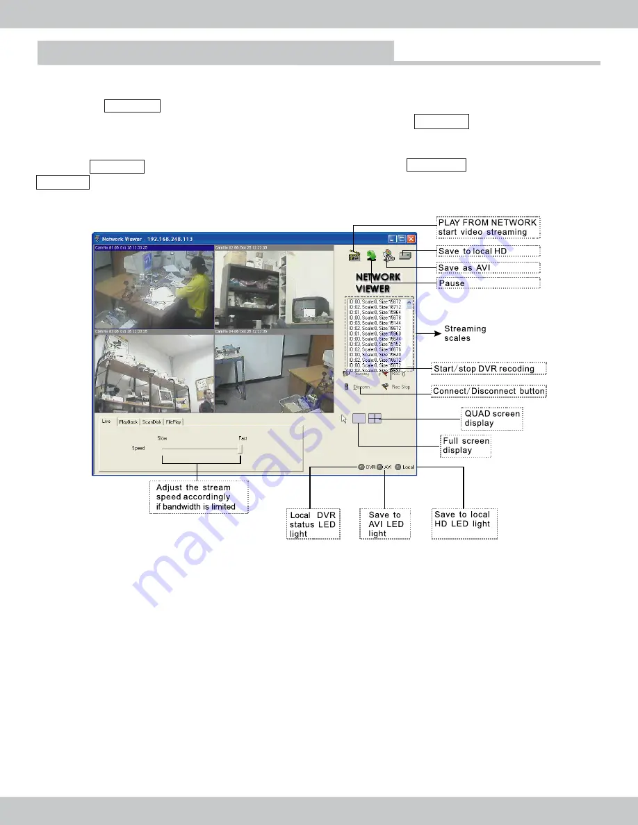
In the save to AVI window, select a save to location and give it a file name.  Next select any 

combination of channels ranging from 1-4 to save and click OK to proceed. A blue LED located in the

Lower-Right hand corner will appear. To stop AVI recording simply press on the “Save As AVI…” again.

Please note, AVI playbacks require window media and the playback speed will be 3 to 4 times faster 

than the actual speed of the original recording. The Netviewer software cannot be used to playback 

AVI files.

To save video streaming to local hard drive: 

Click on the "Save Video Stream to PC's HDD" to start to

save the video to local hard drive.  A green LED located at the Lower-Right hand corner will appear.  To 

stop saving to local hard drive, simply press the “Save Video Stream to PC’s HDD” and the green light 

will disappear and grayed out from the Lower-Right hand corner of Network Viewer.

Note

: The “Save Video Stream to PC’s HDD” saves video format as .dvr which can only be playback

using the “File Play” tab from the Netviewer software. The .dvr video saved to location setting can be

change in the Netviewer setting under the “Local Rec Path”

Click on the Rec Start button to start recording on the local DVR from Network Viewer software and

the red LED light will light up (lower-Right hand corner). Click on the Rec Stop button to stop the DVR

recording and the red DVR LED light will gray out.

Note

: If the local DVR is initially in record mode, then using the Netviewer to remotely connect to the

DVR, the Rec Stop button will not be active or unusable unless the Rec Start. is initiated first then the

Rec Stop can be used to stop the local DVR recording remotely.  The initial record mode from the local 

DVR has the priority over Netviewer software. 

To save video file as AVI format:

 Click on the “Save As AVI…” button located in the upper-right hand

corner of Network Viewer software, a window will appear as illustrated below.

Network Viewer software 

Summary of Contents for NDVR-04

Page 1: ...SecurityMan Network Edition 4CH Triplex Digital Video Recorder User s Manual NDVR 04 SecurityMan ...

Page 2: ...ng workmanship for one year from the date of the purchase If the product is found to be defective then as your sole remedy and as the manufacturer s only obligation SecurityMan will repair or replace the product This warranty is exclusive and is limited to DVR 04 This warranty shall not apply to products that have been subjected to abuse misuse abnormal electrical or environmental conditions or an...

Page 3: ...layback Mode Rec Start Stop Search Event List Search Time Date Search Basic Operation System Set Time Date Set HDD Format Set Auto Sequence Set Factory Reset 15 Play Repeat Video Source Buzzer sound Password Enable New password Video Set Name Setup BRI CON Set Boundary Background Record set Network Set Sensor Set Firmware Update Schedule Set Contents 3 Operation Guide 4 On Screen Display Functions...

Page 4: ...stall 26 How to Use Network Viewer client software Live View Playback Scandisk Fileplay 6 Recording Time 33 Important Message Recording time formula Example Recording size per field Recording time table at PAL Recording time table at NTSC 23 32 32 31 29 27 34 33 35 33 33 33 ...

Page 5: ...watermark during playback mode 10 Down Browse down 11 IR Remote Sensor 12 Enter Select or confirm 13 Menu Setup Mode Menu 14 Playback Pause 15 Stop Stop playback 16 Recording Start or end recording 17 Power on LED indicator Solid Green 18 Recording LED indicator Flashes Red on record The Digital Video Recorder DVR is for recording video streams up to 4 channels all at the same time It adopts the d...

Page 6: ...CONNECTOR 4 VIDEO IN BNC CAMERA INPUT 5 VIDEO LOOP OUTPUT CAMERA LOOP OUT 6 4 sensor inputs and one alarm output 7 DC IN 12V 4 2A positive inside 8 Audio channel input x 1 and audio output x 1 9 LAN network port 10 Power switch 11 NDVR FAN 12 CALL OUT Auto dwell video output to 2nd or son monitor Installation ...

Page 7: ... camera are shown in the figure below Please connect the TV or monitor input source to the video out located on the back of the DVR This unit provide an S Video and 2BNC output connectors Video output are used primary for monitoring and toggle between full screen and quad screen display The call out connector is used for a 2nd or a son monitor output to display full screen single channel with auto...

Page 8: ... internal switch to sound the alarm when the sensor is activated The switch is open at normal state a wiring diagram as shown below When the alarm is activated the switch is closed so that the alarm gets the power The circuitry is shown as in the below figure There are two simple steps to install the alarm a Prepare the power supply for the alarm by connecting the power adapter from the camera to ...

Page 9: ... Display Enlargement During the live view Go to full screen mode by pressing the FULL SEPARATE button and then press the STOP button The freeze symbol F will appear on upper right corner of the screen Then press the ZOOM button the zoom symbol Z will appear on the top right corner of the screen next to F Now you can use the directional buttons to locate the zoomed position up down or left right Pr...

Page 10: ... is the maximum capacity the DVR is capable of detecting Drives that are larger than 2GB capacity can be use but depending on the capacity size of the flash drive the backup speed will vary during backup b Step Two Choose a video file section to save Press PLAY PAUSE button and the Search Mode will appear on screen Please select between REC START STOP SEARCH EVENT LIST SEARCH or TIME DATA SEARCH a...

Page 11: ...they are visible or invisible mark There are 3 types of watermarks to choose from as preferred below During playback mode press the UP button once to activate the invisible watermark Press the UP button twice to activate the visible watermark the visible watermark symbols will appear on the screen as WTNMK as shown in the middle figure below Finally by pressing the UP button third time to activate...

Page 12: ...DVR can store up to 10 files to a page and 100 pages maximum The total files listing up to and date 1000 The START STOP listing delete the rectangular box are arranged in order by time Press the directional button UP DOWN to select a file and press ENTER to confirm the selection and start the playback Operation Guide RECORD SEARCH MASTER PAGE 0001 9999 4 06 2006 14 43 04 26 2006 14 46 ENTER SET EX...

Page 13: ... x4 x8 x16 x32 times for fast forward Press the MENU button to enter the SETUP MODE a variety of menu entities will appear as shown below Press the UP DOWN buttons to highlight selection and press ENTER to confimr selection and the sub menu will appear Press the MENU button to return to the previous screen or to exit from the setup mode On Screen Display Functions SETUP MODE SYSTEM SET VIDEO SET R...

Page 14: ...ay setting can be turn on or off or set to display at the top or at the bottom of the on screen display In the SYSTEM SETUP menu select AUTO SEQUENCE SET and press ENTER Press the directional buttons UP DOWN to select the camera channel and the FORWARD REVERSE buttons to change the sequential dwell time for each channel display Press MENU ESC to return to SYSTEM SETUP TIME DATE SET DATE 0 4 2 6 2 ...

Page 15: ...em setup Repeat play can be used to play cycle playback file FACTORY R D Yes ESET Attention o you want to initialize NO ENTER SET EXIT PLAY REPEAT 15 SYSTEM SETUP TIME DATE SET HDD FORMAT SET AUTO SEQUENCE SET ET FACTORY RES PLAY REPEAT NO VIDEO SOURCE PAL BUZZER SOUND ON PASSWORD ENA OFF NEW PASSWORD 0000 ENTER SET EXIT VIDEO SOURCE United states of america alaska american samoa antigua antilles ...

Page 16: ...E SET FACTORY RESET NO E PLAY REPEAT VIDEO SOURC PAL BUZZER SOUND N O F PASSWORD ENA OF NEW PASSWORD 0000 ENTER SET EXIT PASSWORD ENA In the SYSTEM SETUP menu select PASSWORD ENA to enable or disable the DVR password protection Press the FORWARD REVERSE button accordingly will turn ON OFF the password protection feature When the password it set ON the DVR will request for password whenever the MEN...

Page 17: ...e FORWARD REVERSE buttons to change the alphabet letter charactors There is a maximum of 8 letters numbers entries per channel Press the ENTER OK after completion or browse down to display by pressing the UP DOWN buttons and FORWARD REVERSE to switch between name display ON OFF When finished press MENU ESC to return to VIDEO SETUP menu On Screen Display Functions SYSTEM SETUP IME DATE SET T DD FOR...

Page 18: ...buttons to browse VIDEO SEPUT Press the down button to advance to BACKGROUND selection BOUNDARY BRIGHT CONTRAST SETUP BRI II CON II CAM1 BRI II CON II CAM2 CAM3 CAM4 II BRI II BRI CON II CON II T EXIT ENTER SE In the VIDEO SETUP menu select BACKGROUND Use the directional buttons FORWARD REVERSE to select between black blue gray or white background Press MENU ESC to return to the SETUP MODE or pres...

Page 19: ...SET and press ENTER to enter record setup as illustrated below VIDEO SETUP NAME SETUP BRI CON SET BOUNDARY WHITE BACKGROUND BLUE LANGUAGE ENGLISH ET EXIT ENTER S SETUP M SYSTEM SET ODE VIDEO SET RECORD SET NETWORK SET SENSOR SET FW UPDATE SCHEDULE S T E ENTER SET EXIT RECORD SETUP OVERWRITE YES REC SPEED 50 Fld 1sec REC QUALITY HIGH RESOLUTION 720X240 360X240 PB SPEED 50 Fld 1sec AUDIO ENABLE CAM1...

Page 20: ...ling the client software in the remote computer and there are Router Firewall the same ports 5000 5001 has to be opened from within the Router Firewall in order for the audio video to breach though the Router Firewall to the DVR On Screen Display Functions SENSOR SET Press the MENU button to enter the SETUP MODE select SENSOR SET and press ENTER SETUP MODE T SENSOR SETUP CHANNEL SELECT CAM1 SYSTEM...

Page 21: ...ea There are 48 blocks each are label M stands form motion area Use the directional buttons to choose the area and press ENTER to confirm the selection or ENTER again again to de select the fields Firmware Update M M M M M M M M M M M M M M M M M M M M M M M M M M M M M M M M M M M M M M M M M M M M M M M M NOTE when M is yellow it means that the blocks are selected or active areas The M is white ...

Page 22: ...be used to turn off Schedule Mode go to SCHEDULE SET from the SETUP MODE SCHEDULE SET USB FW UPDATE USB total size 512 MByte Useful size 512 MByte USB Firmware Update SETUP MODE SYSTEM SET VIDEO SET RECORD SET NETWORK SET CONTINUE USB FIRMWARE UPDATE SENSOR SET FW UPDATE SCHEDULE SET Note Only update firmware upon manufacturer s request Press MENU button to enter the SETUP MODE select SCHEDULE SET...

Page 23: ...tall wizard fail to appear please bowse the CD contents and double click on setup exe file to exceute and run setup Select a desire language and then click Next to proceed Press Next to continue the installation To install a different folder click Browse and select another folder Then click Next to continue installation Network Viewer software ...

Page 24: ...24 Setup will add program icons to the program folder listed below Click Next to continue installation Click Next to install NetViewer software Network Viewer software ...

Page 25: ...25 Setup complete Click Finish Network Viewer software ...

Page 26: ...all programs network viewer uninstall Network Viewer or go to the system control panel Add or Remove programs to remove Network Viewer The following windows will appear Click Yes to proceed Network Viewer software Click OK to complete uninstallation ...

Page 27: ...mmand Port to match the local DVR s port settings The video size defaults to half size which has a resolution of 320x240 for 720x240 select full size options Network Viewer software Frame Sec To change the frame rate per second when connecter is establish Enable One Channel Transfer is recommended to transfer single image for better bandwidth control Local Rec Path is to change the recording locat...

Page 28: ...M NETWORK icon located in the upper right hand corner to start live view streaming as illustrated below Press the Disconn disconnect button at any time to stop the live video streaming Click the Connect button and the Logon dialog box will appear The DVR IP address will appear OK to connect in the System field or click down arrow for options Next input the DVR Password and click ...

Page 29: ...er of Network Viewer Note The Save Video Stream to PC s HDD saves video format as dvr which can only be playback using the File Play tab from the Netviewer software The dvr video saved to location setting can be change in the Netviewer setting under the Local Rec Path Click on the Rec Start button to start recording on the local DVR from Network Viewer software and the red LED light will light up ...

Page 30: ... software cannot be used to playback AVI files To save video streaming to local hard drive Click on the Save Video Stream to PC s HDD to start to save the video to local hard drive A green LED located at the Lower Right hand corner will appear To stop saving to local hard drive simply press the Save Video Stream to PC s HDD and the green light will disappear and grayed out from the Lower Right han...

Page 31: ...the DVR s ability to playback important recorded data Please note that this is not one of the remote features used to control the DVR remotely FilePlay tab is used to retrieve saved dvr files from the local hard drive to playback Click on the Open button to browse for dvr files and simply click on the play button in blue and white to start playback Use pause stop REW FF and adjust the playback spe...

Page 32: ...ore with audio recording Recording time calculation formula A Hard disk capacity B Video Quality Low 8Kb frame Normal 10Kb frame High 12Kb frame C Recording Frame Rate 30fps 15fps 10fps 7fps 5fps 4fps etc A GB x 1 000 000 k GB BxC k per sec D sec Recording Time D sec 60 60 24 H days Recording Time For example at NTSC 720 240 Quality Very High 28Kb s Max 30 fps or 60 field sec on a 200GB HDD 200GB ...

Page 33: ... 3 92 6 138 9 231 5 555 6 925 9 1388 9 2777 8 5555 6 Low 57 9 115 7 173 6 289 4 694 4 1157 4 1736 1 3472 2 6944 4 Very Low 61 7 123 5 185 2 308 6 740 7 1234 6 1851 9 3703 7 7407 4 Very High 33 1 High 42 1 Low 51 4 Very Low 57 9 Recording Time Table Based on 320GB HDD at PAL Unit Hours Field Sec Resolution Very High 53 9 107 7 224 5 269 4 538 7 897 9 1346 8 2693 6 5387 2 High 74 1 148 1 308 6 370 4...

Page 34: ... 2 731 0 1462 0 2436 6 3655 0 7309 9 14619 9 Very Low 154 3 308 6 643 0 771 6 1543 2 2572 0 3858 0 7716 0 15432 1 Very High 86 8 High 115 7 Low 138 9 Very Low 154 3 Recording Time Table Based on 500GB HDD at NTSC Unit Hours Field Sec Resolution Very High 82 7 165 3 248 0 413 4 992 1 1653 4 2480 2 4960 3 9920 6 High 115 7 231 5 347 2 578 7 1388 9 2314 8 3472 2 6944 4 13888 9 Low 144 7 289 4 434 0 7...

Page 35: ...www securitymaninc com ...

Reviews: