background image

3 of 16

Model

27-210

Q U I C K   S TA R T

  G U I D E

4

CAUTION

If the included 12-V AC/DC adapter will not be 

used, please go to 

Page 4 

and follow the 

procedure, 

Using a Third-Party Power Source

.

Do not exceed 24 VAC/DC! Failure to choose a 

compatible power source can damage the unit!

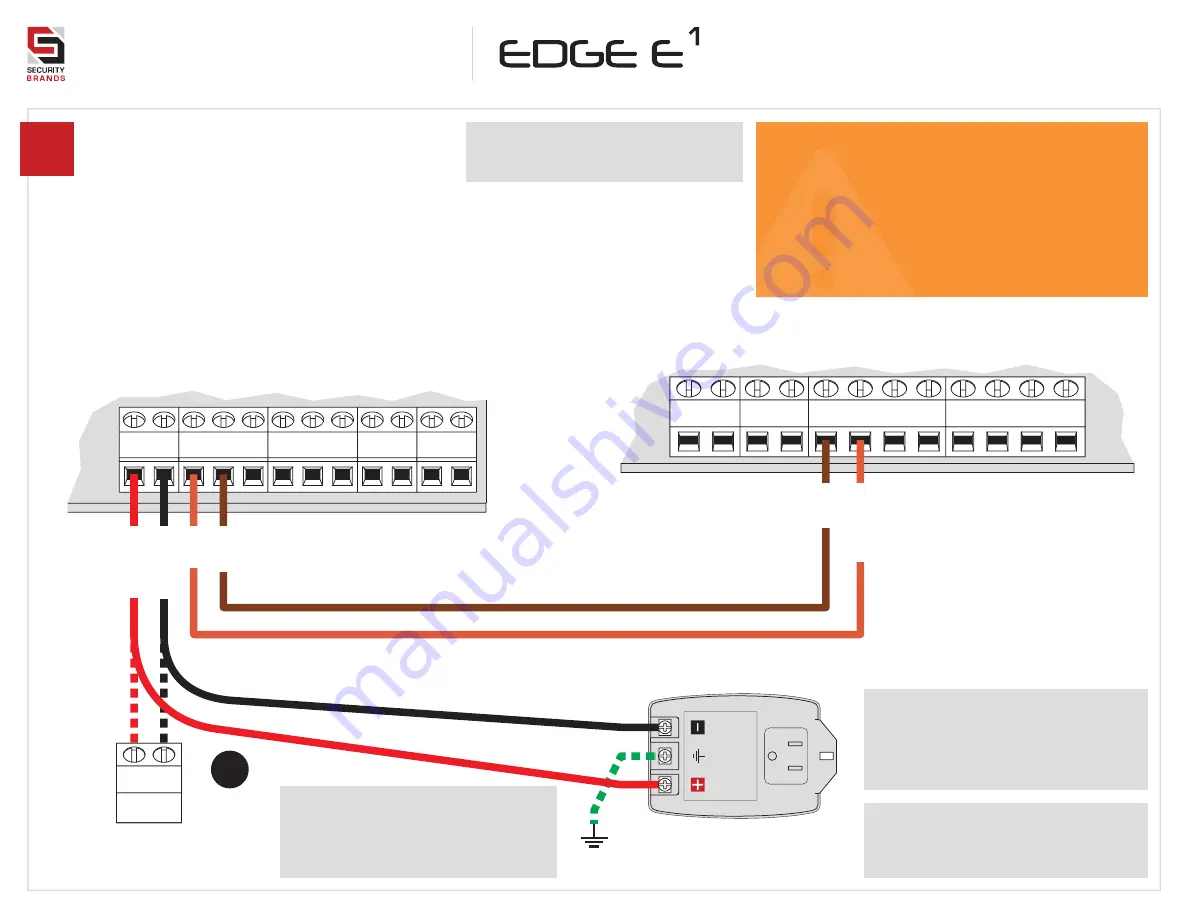
Connect wires.

Feed wires through back of unit, 

and connect as shown using 

included screwdriver.
Excessive force can damage unit!

RELAY A

J10

RELAY B

J11

12–24 VAC/DC

POWER

J3

J17

J5

EVENT INPUTS

Edge Power, Relay, Event Terminals

Gate Operator / Door Opener

POWER (

+)

POWER (

–)

CO

M

RADIO

CO

M

REVERSE LOOP

ST

OP

CLOSE

The GROUND terminal is optional 

unless required by local code(s). 

If using, please connect to earth 

ground or equivalent.

12-V AC/DC Adapter

(Model PS-12DC1 included)

Relay B can be wired to a second device in the same manner.

FREE EXIT

CO

M

N/C

N/C

CO

M

N/O

GND

EVNT2

GND

EVNT1

Consult gate/door opener 

manual for exact connections.
Terminals vary widely across 

manufacturers and models.

If plugging into duplex outlet, 

remove screw from outlet plate, 

and secure with included screw.

Additional wiring diagrams can 

be found on 

Pages 5 and 6

.

+ –

Third-Party 12–24-VAC/DC

Power Source

POS. (

+)

NEG. (

–)

OR

CO

M

N/O

CO

M

OPEN

Summary of Contents for 27-210

Page 1: ...LEAR BEFORE OPERATING REVERSING OR OTHER SAFETY DEVICES SHOULD ALWAYS BE USED Edge Unit Key Carriage Bolt 4x Hex Nut 4x 12 V AC DC Adapter PS 12DC1 Continued on next page Use all four carriage bolts when mounting the unit to a pedestal Leave the antenna in place Seal all openings created in the enclosure Failure to follow these instructions can damage the unit and or cause it not to function corre...

Page 2: ...Page 6 Reset Button For performing unit reset Power Relay Event Terminals For wiring to power wiring to gate operator or door opener and connecting request to exit devices See Pages 3 and 5 Card Reader Mounting Location For mounting Wiegand proximity card reader sold separately See Edge E3 Quick Start Guide or Edge Direct Programming Manual for programming instructions Relay Status LEDs Relay is a...

Page 3: ...nt Terminals Gate Operator Door Opener POWER POWER COM RADIO COM REVERSE LOOP STOP CLOSE The GROUND terminal is optional unless required by local code s If using please connect to earth ground or equivalent 12 V AC DC Adapter Model PS 12DC1 included Relay B can be wired to a second device in the same manner FREE EXIT COM N C N C COM N O GND EVNT2 GND EVNT1 Consult gate door opener manual for exact...

Page 4: ...ird Party Power Source Optional Before going forward double check all wiring and make sure the unit has power Wiring diagrams for connecting to accessory devices can be found on Pages 5 and 6 For connecting accessories not mentioned please contact Technical Support Make sure the gate or door path is clear before completing Step 7 Add Access Code to Relay A To add multiple codes enter each of them ...

Page 5: ...oor Switch Event Inputs Wiring for accessories such as a request to exit device RELAY A J10 RELAY B J11 12 24 VAC DC POWER J3 J9 J5 EVENT INPUTS Edge Power Relay Event Terminals N C N C COM N O GND EVNT2 POS NEG COM N O GND EVNT1 Alarm Contact To Alarm System Event Input configuration instructions can be found on Pages 10 and 11 Digital Inputs can be configured using the Edge Smart Keypad app ...

Page 6: ...ND LED2 LED1 DAT0 DAT1 12V DOOR READER A WIEGAND 1 DOOR READER B WIEGAND 2 Disconnect power to the Edge unit before connecting Wiegand devices Failure to disconnect power can damage the unit Wiegand Device Wiring for a Wiegand device Wiegand configuration instructions can be found on Page 14 If mounting a Wiegand card reader to the Edge unit front panel remove the existing cover plate and hex nuts...

Page 7: ...steps on this page for downloading it Step 2 Fill out your account information and tap the Sign Up button If you have already created an account you will log in instead Step 3 On the Paired Keypads screen tap the Add Keypad button Step 4 On the Add Keypad screen tap the Edge unit you want to pair If you do not see any Edge units listed make sure your Edge unit is powered on and is in Bluetooth ran...

Page 8: ...y purposes Programming Sub Modes 1 Add Access Code s to Relay A 2 Delete Code Non Wiegand 3 Change Master Code 4 3 Add Latch Code to Relay B 4 4 Change Sleep Code 4 5 Change Code Length Non Wiegand 4 6 Change Relay Trigger Time 4 7 Enable Disable Timers and Schedules 4 8 Enable Disable 3 Strikes You re Out 4 9 Configure Event Input 1 5 Add Latch Code to Relay A 6 Configure Wiegand Inputs 7 Add Acc...

Page 9: ...second lockdown for 90 seconds when an incorrect code is entered three times Current State On 1 beep Off 2 beeps 1 1 2 5 Master Code 1251 is default Sub Mode A Sub Mode B 7 4 Configure 1 for no change 2 to change state Enable Disable Timers and Schedules Change Relay Trigger Time Sub Mode A Sub Mode B 6 4 1 1 2 5 Master Code 1251 is default Trigger Time in Seconds 001 999 Relay 1 for A 2 for B Sub ...

Page 10: ...elay A or Relay B when event input state changes from normally open N O to normally closed N C Mode 2 Log Mode Makes log entry of event input state when event input state changes from normally open N O to normally closed N C Mode 3 Remote Open and Log Mode Combines Modes 1 and 2 Mode 4 Arming Circuit Mode Enables either Relay A or Relay B when event input state changes from normally open N O to no...

Page 11: ...d 1 1 2 5 Master Code 1251 is default Sub Mode A Sub Mode B 9 4 Event Mode 0 Current State Unit beeps mode number or good tone when disabled 1 1 2 5 Master Code 1251 is default Sub Mode A Sub Mode B 9 4 Event Mode 2 Mode 5 Mode 2 Disable Event Digital Inputs Mode 0 Configure Event Input 1 continued Allows an external device to affect keypad operation or trigger a relay To configure additional input...

Page 12: ... good tone before moving on Configure Wiegand Input Allows enabling or disabling of a Wiegand input and configuration of the Wiegand device type For the tag reader type use the Edge Smart Keypad app Sub Mode A Wiegand Input 1 for 1 2 for 2 6 1 Configuration 0 for disabled 1 for keypad 2 for card reader 3 for remote 1 2 5 Master Code 1251 is default 0 5 0 Sub Mode B Sub Mode A 6 1 1 2 5 1 Master Co...

Page 13: ...o Be Added 4 digits by default numbers only Master Code 1251 is default Add Latch Code to Relay A Add Limited Use Code Access codes can be given a use or time restriction For more advanced time restrictions use the Edge Smart Keypad app Code to Be Added 4 digits by default numbers only Sub Mode Restriction Type 1 for uses 2 for time 8 1 1 2 5 Uses Time 01 99 uses or 01 24 hours Master Code 1251 is...

Page 14: ...to Be Added 5 digits by default numbers only Master Code 1251 is default Relay 100 for A 104 for B On Wiegand Input 1 or 2 On Both Wiegand Inputs Green arrow indicates good tone on unit Always wait for good tone before moving on Sub Mode A 6 1 Sub Mode C 1 1 2 5 Code s to Be Added 5 digits by default numbers only Master Code 1251 is default Add Wiegand Keypad Manager Access Code s Uses default fac...

Page 15: ... 1 for 1 2 for 2 6 1 Sub Mode B 1 1 2 5 Code s to Be Added 5 digits by default numbers only Master Code 1251 is default Relay 103 for A 105 for B On Wiegand Input 1 or 2 On Both Wiegand Inputs Sub Mode A 6 1 Sub Mode C 1 1 2 5 Code s to Be Deleted 5 digits by default numbers only Master Code 1251 is default Delete Wiegand Keypad Code s Uses default facility code to delete multiple codes enter each...

Page 16: ... Email techsupport securitybrandsinc com We are available Mon Fri 8am 5pm Central 2021 Security Brands Inc All rights reserved Model 27 210 16 of 16 QSG 27210 EN Rev C 2 2021 QU ICK STA R T GU I DE Edge E1 27 210 Notes ...

Reviews: