9
500-10420, Rev G
1. INSTALL the blind nuts using the provided collapsing tool.
a. INSERT the assembled blind nut and installation tool into a mounting
hole to install a blind nut into the 3/8” [9.5 mm] hole (see Figure 8).
b. HOLD the install nut using a 1/2” [13 mm] box-end wrench and, at the
same time, COLLAPSE the blind nut using a 3/16” [5.0 mm] hex wrench
to turn the socket cap screw (see Figure 9).
NOTE:
The collapsing tool is reusable for several blind nut installations.
c. REMOVE the collapsing tool when finished.
NOTE:
Once installed, the blind nuts leave a threaded insert that will accept
the case-hardened machine screws provided in the hardware pack.
d. VERIFY that the blind nut is properly collapsed (see Figure 10).
Install the Strike Plate
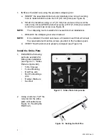
1. ENSURE the following
parts are available for
strike plate installation
(see Figure 11, “Strike
Plate Components”):
• 5/16-18
screw
• Funnel
Bushing
•
Roll Pins (2X)
•
Roll Pin Bushings
(2X)
• Rubber
Washers
• Sex
Bolt
Figure 11. Strike Plate Components
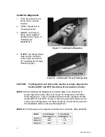
2. Using a hammer, TAP the
roll pins into the strike
plate until seated (see
Figure 12, “Seating the
Roll Pins”).
Figure 12. Seating the Roll Pins

