background image

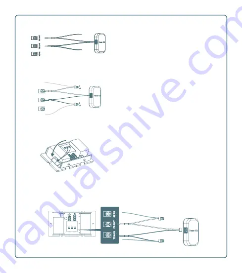
Connect the END of the WHITE wire to 

the original FRONT wire, twisting a wire 

connector cap onto the two wires to 

secure them together.

Connect the END of the BLACK wire 

to the original TRANS wire and twist 

together with a wire connector cap. 


REAR TRANS FRONT

Wiring Overview

Stick the power kit module to the side of 

your mechanical chime using the 2-sided 

tape on the back of the module.

Replace the chime cover.

Wire the MID-POINT “V” part of the 

WHITE wire to the FRONT terminal and 

tighten the screw to secure it.

Wire the MID-POINT “V” of the BLACK 

wire to the TRANS terminal and tighten 

the screw to secure. 

Original FRONT wire

Original TRANS wire

Summary of Contents for OKO DB3A

Page 1: ...Quick Start Guide POWERED BY OKO 3MP DOORBELL CAMERA DB3A ...

Page 2: ......

Page 3: ...the camera is on and ready for Wi Fi connection Steady blue the camera is running properly Steady red the camera is starting Flashing red there is a network connection issue STATUS INDICATOR Getting to know the camera LENS PIR MOTION DETECTOR STATUS INDICATOR CALL BUTTON ...

Page 4: ...ED WIRES 8 DRILL BIT MINI LEVEL What s in the box 4 POWER KIT WIRE HARNESS 2 ADDITIONAL FACEPLATE 3 MOUNTING PLATES PLATE FOAM 6 FUSE WIRE WIRE CONNECTORS MOUNTING SCREWS ANCHORS SECURITY SCREWS FIXING SCREWS DOORBELL SCREWS 9 10 11 12 13 14 ...

Page 5: ...nnected Remove the cover from the chime box Locate the terminals labeled TRANS and FRONT Loosen the screws and disconnect both wires Installing the chime power kit In your doorbell accessories locate the wireless power kit module and connect it to the black and white wiring harness via the small white plug on the end Requires an existing mechanical chime or a digital chime with TRANS and FRONT ter...

Page 6: ...wire connector cap REAR TRANS FRONT Wiring Overview Stick the power kit module to the side of your mechanical chime using the 2 sided tape on the back of the module Replace the chime cover Wire the MID POINT V part of the WHITE wire to the FRONT terminal and tighten the screw to secure it Wire the MID POINT V of the BLACK wire to the TRANS terminal and tighten the screw to secure Original FRONT wi...

Page 7: ... desired location Mark drill points on the wall with a pencil Mounting the doorbell camera If mounting the doorbell to a concrete surface drill holes into the wall at the drill points using the included drill bit then insert the screw anchors If mounting to a wooden surface the anchors will not be required Use a smaller drill bit not included to drill pilot holes directly into the wall The bubble ...

Page 8: ...ach the fuse wire to an existing doorbell wire then to the opposite end of one of the U wires twisting the wires together with wire connector caps Attach the other U wire to the remaining existing doorbell wire and twist together with a wire connector cap Connect the U end of each U wire to the terminals on the back of the doorbell Tighten into place with the fixing screws OR Wiring the doorbell c...

Page 9: ...nto the mounting holes in the doorbell and tighten to fix the doorbell to the mounting plate Optional Insert a MicroSD card into the MicroSD card slot on the side of the camera The card will be formatted during the add camera process Place the faceplate back on the doorbell camera Locate the two tiny security screws and carefully insert them one at a time into the bottom of the faceplate tightenin...

Page 10: ...he camera to your account and configure the network settings Resetting the camera If you change your Wi Fi network or for some other reason you cannot connect to the camera you will need to reset it Using the included screwdriver carefully remove the two security screws at the bottom of the faceplate then remove the faceplate Press and hold the Reset button for 10 seconds In the app go to the Sett...

Page 11: ......

Page 12: ......

Reviews: