background image


MAN_Easyflex_com_eng_01.doc 


35 

3.8.3 

How to Determine an Unknown Nominal Velocity of 

Propagation or Pulse Propagation Velocity  

When  the  nominal  velocity  of  propagation  or  pulse propagation velocity of 
the faulty cable is not known, a test sample of the same type of cable with 
known  length  is  needed  (or  the  distance  to  a  specific  point  in  the  cable 
must be known). 

Set  the  cursor  to  the  foot  point  of  the  known  reflection.  Then  adjust  the 
NVP  or  pulse  velocity  setting  such  that  the  indicated  distance  to  the  fault 
correlates with the actual length of the sample. After that the distance to a 
fault reflection in the defective cable can be measured.  

3.8.4 

Simplification of Fault Location Using Comparative Tests 

The  reflectogram  shown  in  Fig  6  shows  cable  and  fault  in  virtually  ideal 
conditions.  In  reality,  however,  there  are  cable  junctions  and  other 
connections  resulting  in  a  trace  which  is  normally  similar  to  that  shown  in 
Fig 7 (good pair). In Fig.  8 (Faulty pair), in addition to the fault other cable 
reflections are visible which are caused commonly by connections with an 
impedance  different  from  that  of  the  line.  These  jumps  in  impedance  also 
appear as reflections and thus render the detection of the reflection caused 
by  the  fault  almost  impossible.  When  a  multi-pair  cable  is  tested,  a 
comparative  test  (see  Fig  9)  using  a  good  pair  (provided  that  not  all 
conductors are defective) allows the point of fault to be detected. Connect 
the good pair to L2, the faulty pair to L1. Then select mode Alt by pressing 
key  (Line).  Move  the  cursor  to  the  points  where both trace diverge. In Fig 
10  mode  Diff  was  used  which  means  that  differences  between  both 
reflectograms (fault reflections in the defective cable) occur in places where 
the  difference  on  display  deviates  from  the  horizontal.  Use  the  cursor  to 
measure the distance to the foot point of the deviation.  


Summary of Contents for Easyflex Com

Page 1: ...kationsnetze Communication Networks Elektrizit tsnetze Power Networks Rohrleitungsnetze Water Networks Leitungsortung Line Location Date of release 2003 34 Mess und Ortungstechnik Measuring and Locati...

Page 2: ...2 MAN_Easyflex_com_eng_01 doc...

Page 3: ...MAN_Easyflex_com_eng_01 doc 3 Easyflex Com compact and light weight Time Domain Reflectometer...

Page 4: ...4 MAN_Easyflex_com_eng_01 doc...

Page 5: ...tion 28 3 8 How to Locate a Fault 29 3 8 1 Fields of Application 30 3 8 1 1 Faults Causing a Negative Reflection 30 3 8 1 2 Faults Causing a Positive Reflection 31 3 8 1 3 Further Fields of Applicatio...

Page 6: ...46 4 2 Operation 47 4 2 1 Safety Precautions 47 4 2 2 Modes of Operation 47 4 2 3 Practical Hints 48 4 3 Troubleshooting 49 5 CARE UND MAINTENANCE 49 6 APPENDIX 50 6 1 List of Abbreviations Used 50 6...

Page 7: ...ification test performed by the department of Quality Assurance of Hagenuk KMT Kabelmesstechnik GmbH Conformance with the directive on Electromagnetic Compatibility was verified in accordance with the...

Page 8: ...8 MAN_Easyflex_com_eng_01 doc...

Page 9: ...471 Radeburg Dresden D 96148 Baunach TELEFON 49 35208 84 0 TELEFON 49 9544 68 0 TELEFAX 49 35208 84 249 TELEFAX 49 9544 22 73 SERVICE HOTLINE TELEFON 49 35208 84 211 TELEFON 49 9544 68 0 TELEFAX 49 35...

Page 10: ...uk KMT Warranty claims on Hagenuk KMT lapse 12 months after the delivery date Parts supplied by Hagenuk KMT within the framework of the warranty are also covered by this warranty for the remaining war...

Page 11: ...staff Other persons must be kept away This manual must be available for the supervisory operating and maintenance staff to refer to Improper use may endanger life and limb the Easyflex Com and connect...

Page 12: ...dead and then only by a skilled electrician in accordance with current accident prevention regulations A skilled electrician in the sense of the accident prevention regulations is a person who can ass...

Page 13: ...the connected test object In every place where the electric characteristics of the cable have changed part of the transmission pulse is reflected and caused to travel back to the Easyflex Com where i...

Page 14: ...pairs Location of crosstalk NEXT Pair versus Pair k1 measurement There are two display modes the user can choose between When you wish to get a revealing overview of the cable under test and at the s...

Page 15: ...out alternately on cables connected to sockets L1 L2 Diff Measurement of difference between cables connected to sockets L1 and L2 NEXT Location of crosstalk between cables connected to sockets L1 and...

Page 16: ...e 4000 m 2 5 m for range 7500 m 5 m for range 15 km Accuracy 0 1 of range of measurement 1 cursor step Gain 0 80 dB in steps of 1 dB Dynamic range 90 dB Distance reading m ft or s Setting range of sig...

Page 17: ...h of test inputs 250 V AC DC 50 60 Hz CAT II overvoltage category Memory locations 16 Measuring rate up to 11 reflectograms per second averaging mode short range Display rate up to 4 screen images per...

Page 18: ...orage temperature accumulator 20 C 50 C Dimensions mm 176 x 260 x 70 L x W x H 186 x 260 x 70 incl measuring terminals Weight approx 1 5 kg Interelement protection class II with accumulator compartmen...

Page 19: ...of Easyflex Com G E two languages on request 2 pcs set of test leads Case for Easyflex Com Accumulator 7 2 V 1 7 Ah NiMH Charge case Plug in mains unit for charger case according to country EURO 230...

Page 20: ...the on site preparation of test reports Transportation case for printer set Plug in mains unit external source of power Adapter cable for charging the accumulator from a vehicle electric mains using...

Page 21: ...a reference for comparison with the test object connected to L1 In mode Diff this facilitates the detection of small fault reflections in the tested line connected to L1 because each reflection cause...

Page 22: ...the reflectograms Press Display when you want to work with two images of the trace see Fig 3 The upper is the reflectogram of the full range of measurement There is a black bar below this overview ind...

Page 23: ...r operation Replace the accumulator or charge it in order to restore readiness for operation Switch the instrument off before replacing the accumulator to retain all data Press one of the following ke...

Page 24: ...y the Easyflex Com will display informations on one of the following topics key select with rotary encoder press key Mark key for return Information on help Fault location Operation Compensation Avera...

Page 25: ...Zoom Propagation velocity NVP Single or Dual Display Menu Menu Units Menu Interface Menu Printer Menu System Menu Power supply Help Cursor Range Measuring Range Gain dB Compensation Modes Single Cont...

Page 26: ...d Menu Printer Printer Layout HP Deskjet Epson compatib Epson 9 pin Kodak Diconix Normal Special Menu System Self test Date time Language Software version Serial number mm dd yy hh mm ss AM PM German...

Page 27: ...r s logo will be shown for about 2 seconds After run up has been completed the Easyflex Com can be switched off any time by pressing key When being switched off the device saves all device settings so...

Page 28: ...o as to be able to detect and locate a fault at close range i e at a distance of up to 10 meters When a faultless pair of conductors of the same type of cable as the faulty one is available and when i...

Page 29: ...ent and do not remove the cap of the serial interface 3 The Easyflex Com is able to measure the length of the cable and the distance to a point of fault It is not able however to find out the route of...

Page 30: ...egative reflection see Fig 4 Fig 4 Type of Fault Causing a Negative Reflection 2 Short circuit to shield One conductor in a cable is in contact with the metal shield of the cable For locating this typ...

Page 31: ...me detached To locate such faults and to suppress noise signals on the display connect the test leads to the shield and to as many conductors of the cable as possible This type of fault generates a fa...

Page 32: ...roken line Moisture in a cable filled with petrolatum may possibly result in very small fault reflections as the volume of moisture is only limited 3 8 1 3 Further Fields of Application 1 T joints Tap...

Page 33: ...e 2 3 Press key to switch the Easyflex Com on Menu Measurement will appear after a few seconds 4 Press key Line to select the appropriate mode of measurement e g Diff when a good pair is available or...

Page 34: ...ch that the reflection is located above the bar Then use the rotary encoder to move the cursor in the lower part of the screen to the place where the foot point of the fault is located see Fig 6 10 Th...

Page 35: ...able junctions and other connections resulting in a trace which is normally similar to that shown in Fig 7 good pair In Fig 8 Faulty pair in addition to the fault other cable reflections are visible w...

Page 36: ...to solve this problem the Easyflex Com is equipped with an averaging mode Press function key Mode and use the rotary encoder to enable mode Averaging The display will display the number of measuremen...

Page 37: ...ance the device can determine the beginning and the end of a split pairs section in a longer trunk line which is composed of a number of sections The point of crosstalk coupling is located as in any n...

Page 38: ...en a cable is composed of sections with differing NVP v 2 values for measurements in relation to a known point of reference this will increase measuring accuracy and for determining the NVP v 2 value...

Page 39: ...00 ns 4 km 200 ns 200 750 3000 ns 7 5 km 750 ns 750 3000 ns 15 km 750 ns 750 3000 ns The offered combinations of pulse width and display range take into account that not every pulse width is suitable...

Page 40: ...ice to have the Lithium accumulator replaced Error code 2 asks for setting the clock 2nd Menu Menu System Mark go with rotary encoder to Date Time Mark select unit of time with rotary encoder Mark sel...

Page 41: ...y change of the v 2 setting will also change this value in the reflectogram When a trace is loaded v 2 is re set to its stored value In mode ALT two adjacent memory locations are made available for st...

Page 42: ...in front of Cursor Use key combination 2nd Recall for a quick download of a trace from memory location 1 The traces stored in memory can later be used for processing or for printing out a hardcopy It...

Page 43: ...extra is installed on the PC Winkis Com can also be used for re loading a reflectogram including its set up Furthermore Winkis Com gives you access to all reflectograms stored Please refer to the sof...

Page 44: ...tput voltage 12 V DC Interelement protection class II Operating temperature range 0 40 C Storage temperature range 40 70 C Charger Input voltage 12 0 V DC Maximum input current 580 mA Interelement pro...

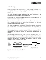
Page 45: ...arger circuit see enlarged details The amber indicator lamp shall light up continuously after the accumulator has been inserted If it does not shortly disconnect the charger from the mains After charg...

Page 46: ...er Case 4 1 3 General Instructions on How to Handle a NiMH Accumulator ATTENTION Do not short circuit a accumulator Do not dismanntle or modify a accumulator Do not dispose of in fire Protect batterie...

Page 47: ...ose vicinity of storage media Only use the plug in mains unit supplied 4 2 2 Modes of Operation OPERATION The green LED is alight Indicates that the charger is ready for use STATUS Waiting mode The am...

Page 48: ...has been completed the device will change over to trickle charging to compensate for natural self discharge The optimum way of operation is to have two accumulators with one remaining in the charger...

Page 49: ...solve the problem please submit the device to your service station for inspection or contact the Hagenuk KMT hotline 5 CARE UND MAINTENANCE Neither the Easyflex Com nor any of its accessories contain...

Page 50: ...agnetic compatibility IEC International Electrotechnical Committee LCD Liquid crystal display LED Light emitting diode NEXT Near end cross X talk NiMH Nickel metal hydrid NVP Nominal velocity of propa...

Page 51: ...MAN_Easyflex_com_eng_01 doc 51 6 2 Conversion NVP v 2 Conversion NVP v 2 m s 2 s m 299 79 NVP 2 v Conversion v 2 m s NVP s m 299 79 2 v 2 NVP...

Page 52: ...Insulation v 2 m s v 2 ft s NVP Oil impregnated paper 75 84 246 276 0 50 0 56 Poly cross linked 78 87 256 285 0 52 0 58 Poly filled with Petrolat 96 0 314 8 0 64 Polyethylene 100 5 329 6 0 67 PTFE 106...

Page 53: ...MAN_Easyflex_com_eng_01 doc 53 From your own measurements Propagation time Insulation or type of cable v 2 m s v 2 ft s NVP...

Page 54: ...ansmitter signals A pulse is an electrical signal with high amplitude and short duration When travelling along the cable each pulse is more and more deformed attenuation of amplitude increase in signa...

Page 55: ...faktor in German is a way to describe the propagation velocity of a signal along a line It specifies the ratio of signal propagation velocity to the velocity of light If for instance the NVP of a cabl...

Page 56: ...ich is enclosed in a common shield Balanced Line Two wire line with the voltages of either conductor versus earth being equal in size but opposite in polarity Usually two wire line are twisted twisted...

Page 57: ...e this is a usual way of taking twice the signal travel path into account To depict a reflection on the screen the signal has to travel from the meter to the fault and back If the v 2 values of variou...

Reviews: