


Yellow "Busy" LED
Continuously
It is on during device communication.
Blue "Inputs" LED
Inputs
Status of inputs, indicates whether the the inputs are active.
White "Outputs" LED
White
Status of outputs, indicates whether the relays are triggered.
3. Connection and installation of the
MobilGate-128c
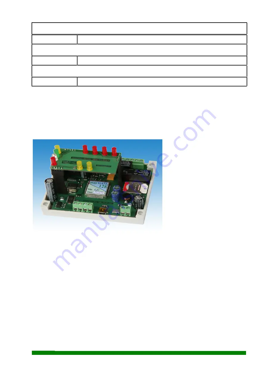
The connection points of the interface can be found in the figure below:
Up: High current relay outputs
Down: USB connectors
Input connectors
Power supply connector
The power connection needs 10-
30V DC supply voltage. The inputs
of the
MobilGate-128
gate controller
can be triggered by connecting it a
5-30Vdc voltage on the opto isolated
inputs. The numbering of the module
inputs is marked on top of enclosure.
It has high current No-Com-Nc type
relay outputs and their maximalum
load is 230V and 8A. The No, Com
and Nc points of the relays are wired out. The GSM modem has a screwed SMA aerial connector
and a small-sized pole aerial or an aerial with a coax cable or similar plug can also be installed to it.
The power input of the GSM gate opener module is protected against reverse polarity and it
is equipped with 500mA multifuse. The input voltage on the general purpose inputs ranges is from
5V ... 30Vdc.
4.
Configuring MobilGate-128c using a computer:
MobilGate-128c
can be configured with computer or notebook via USB-port by using our
free software. A SIM card that is able to send SMS and it is not protected with PIN code has to be
isrequired for Windows XP or any newer operation system. After driver installation, the next step is
inserted into the module. When the device is connected to the USB-port, the module driver has to be
SeaSoft Ltd.
www.seasoft.hu - www.mobil-control.eu T: (+36) 62 406405 M: (+36) 30 2557688 F: (+36) 62 405-969


