background image

ELECTRICAL

WIRING CONNECTIONS

Fire hazard. 

Incorrect voltage can cause a fire or

seriously damage the motor and voids the warranty. The supply
voltage must be within ±10% of the motor nameplate voltage.

NOTICE: Dual-voltage motors are factory wired for 230 volts. If nec-
essary, reconnect the motor for 115 volts, as shown. Do not alter
the wiring in single voltage motors.

Install, ground, wire, and maintain your pump in compliance with
the National Electrical Code (NEC) or the Canadian Electrical Code
(CEC), as applicable, and with all local codes and ordinances that
apply. Consult your local building inspector for code information.

Connection Procedure:

1. Connect the ground wire first as shown in Figure 9. The ground

wire must be a solid copper wire at least as large as the power
supply wires.

2. There must be a solid metal connection between the pressure

switch and the motor for motor grounding protection. If the
pressure switch is not connected to the motor, connect the
green ground screw in the switch to the green ground screw
under the motor end cover. Use a solid copper wire at least as
large as the power supply wires.

3. Connect the ground wire to a grounded lead in a service panel,

to a metal underground water pipe, to a metal well casing at
least ten feet (3M) long, or to a ground electrode provided by
the power company or the hydro authority.

4. Connect the power supply wires to the pressure switch as

shown in Figure 6. 

5. Reinstall the pressure switch cover.

6

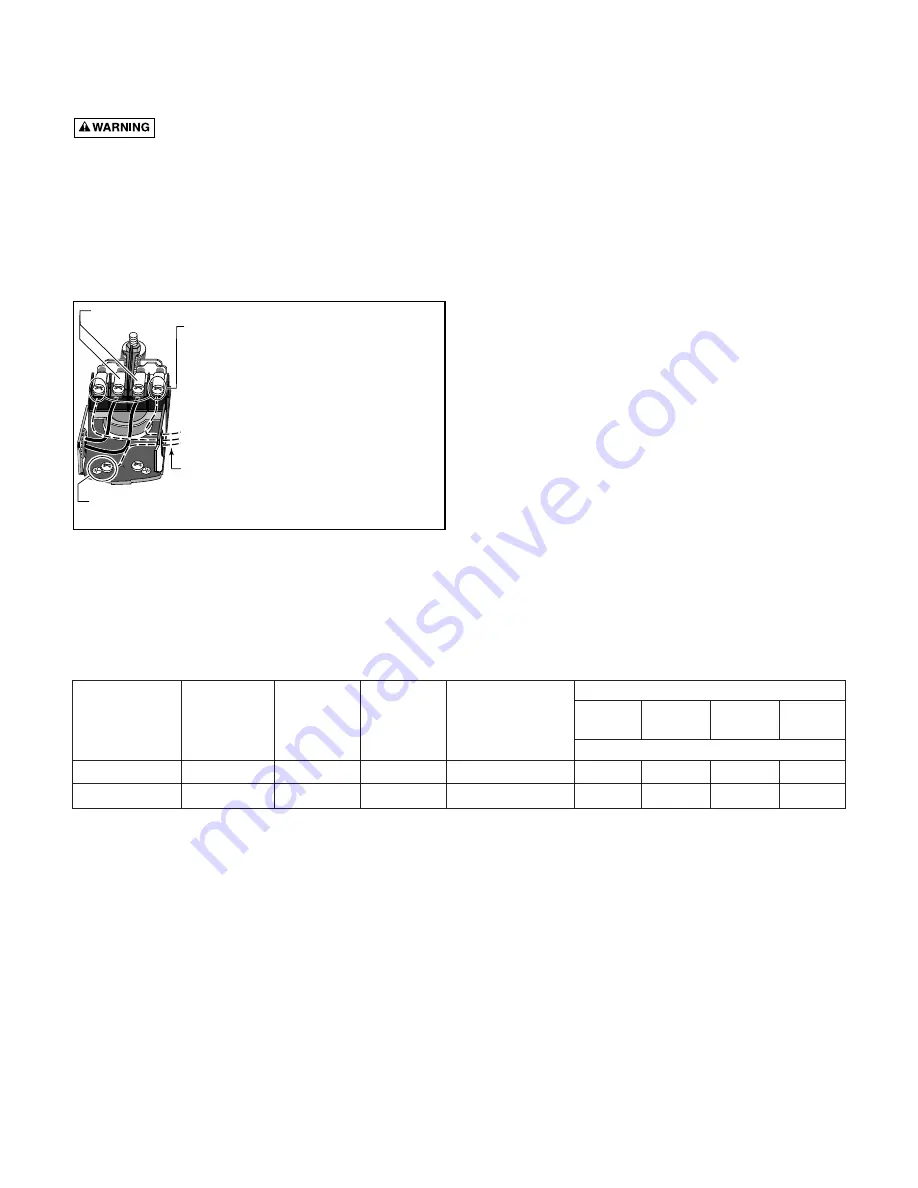
FIGURE 6 – Pressure switch wiring

Clamp the power cable to prevent strain 
on the terminal screws.

Connect the green (or bare copper)  ground wire 
to the green ground screw.

Motor wires 

connect here

.

3187 0398

Power supply wires

 connect here. 

230 Volt:

 Connect 2 hot wires (black and red)

here and cap the white (neutral) wire. It does
not matter which wire goes to which screw. 

115 Volt:

 Connect one hot wire (black or red)

to one of these screws (it doesn't matter 
which one). Connect the white (neutral) wire 
to the other screw. Cap any remaining 
black or red wires.

TABLE II – RECOMMENDED FUSING AND WIRING DATA

Distance in Feet From Motor to Meter

Branch 

0 to

51 to

101 to

201 to

Motor

Max. Load

Delayed Fuse

50

100

200

300

Pump Model

Horsepower

Volts

Amperes

Rating Amps

Wire Size

390.2514

1/2

115/230

10.5/5.2

15/15

14/14

14/14

10/14

8/14

390.2518

3/4

115/230

12.4/6.2

20/15

12/14

12/14

10/14

8/14

Summary of Contents for CRAFTSMAN HYDROGLASS 390.2514

Page 1: ...Instructions Before First Use of This Product Save This Manual For Future Reference Sears Roebuck and Co Hoffman Estates IL 60179 U S A Safety Instructions Installation Operation Troubleshooting Repai...

Page 2: ...k burn or cause death Ground pump before connecting to power supply Hazardous pressure Install pressure relief valve in discharge pipe Release all pressure on system before working on any component Pe...

Page 3: ...anty 9 Make sure the line voltage and frequency of the electrical circuit supply agree with the motor wiring If motor is dual voltage type BE SURE it is wired correctly for your power supply 10 The co...

Page 4: ...he pump is over well This will be less if pump is offset from the well Both figures are for sea level The maximum lift of any pump decreases with the elevation above sea level This decrease is at the...

Page 5: ...the one at right Dial Type Voltage Selector To change to 115 volts 1 Make sure power is off 2 Turn the dial counter clockwise until 115 shows in the dial window 3 Reinstall the Motor end cover 4 Go t...

Page 6: ...ire at least as large as the power supply wires 3 Connect the ground wire to a grounded lead in a service panel to a metal underground water pipe to a metal well casing at least ten feet 3M long or to...

Page 7: ...ded fittings in the plastic pump If leaks do occur remove the fitting replace the Teflon tape and rewrap with 1 1 2 to 2 turns of Teflon tape and remake the connection 2 Independently support all pipi...

Page 8: ...side with plastic mallet This will insure proper seating of O Ring and clamp E Assemble base mounting bolts Connect pressure switch tub ing and close draincock F Prime pump and turn on power REMOVING...

Page 9: ...e proceed as follows 1 Disassemble pump per instructions on Page 8 2 Turn venturi counterclockwise and remove it The nozzle is now exposed Remove it using a 5 8 hex socket wrench with extension Turn c...

Page 10: ...6 7 8 10 9 11 12 13 14 15 16 17 18 19 20 21 22 23 24 25 25A 26 27 28 29 766 1194 To Order Parts in the U S A Call Sears Product Service 1 800 366 7278 To Order Parts outside the U S A Call Your local...

Page 11: ...7 8 5 Required U43 21SS 8 Star Washer 5 Required 10 C19 54SS C19 54SS Clamp Tank Body 11 U9 201 U9 201 O Ring Venturi 1 3 8 x 1 1 8 x 1 8 12 N32P 66 N32P 66E Venturi 13 N34P 19 N34P 17 Nozzle 14 N76...

Page 12: ...h plastic pipe where possible otherwise with point 3 immediately limed causing excess friction new steel pipe above 3 Offset piping is too small in size 3 Use larger offset piping Pump pumps water 1 P...

Page 13: ...13...

Page 14: ...14...

Page 15: ...15...

Page 16: ...all 9 am 5 pm Monday Saturday 1 800 827 6655 M A I N T E N A N C E A G R E E M E N T America s Repair Specialists REPAIRSERVICES America s Repair Specialists REPAIRSERVICES America s Repair Specialist...

Reviews: