

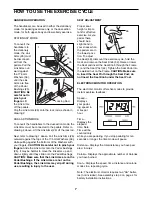


Follow the steps below to use the electronic monitor:
1. To turn on the power, press the on/off button or
simply begin pedaling.
2. Select one of the five modes:
A. ScanÑ
When the
power is
turned on,
the scan
mode will
be select-
ed auto-
matically.
A mode
indicator
will appear
by the
word "SCAN." The speed, time, distance and calo-
rie modes will all be displayed, for five seconds
each, in a repeating cycle. A second mode indica-
tor will show which mode is currently displayed.
B. Speed, time, distance or calorieÑTo stop the
scan mode and select the speed, time, distance or
calorie mode for continuous display, repeatedly
press the mode button. Make sure that there is not
a mode indicator by the word ÒSCAN.Ó The modes
will be selected in the following order: speed, time,
distance, calorie, scan.
3. To reset the display, turn the power off and then on
again by pressing the on/off button twice.
4. When you are finished exercising, press the on/off
button to turn off the power.
Note: If the pedals
are not moved and the buttons are not pressed
for four minutes, the power will turn off auto-
matically in order to conserve the batteries.
8
Inspect and tighten all parts of the exercise cycle regu-
larly. To clean the exercise cycle, use a damp cloth
and mild detergent. Never use abrasives or solvents;
keep liquid away from the console.
ELECTRONIC MONITOR
If the electronic monitor does not function properly, the
batteries should be replaced. Most problems are the
result of drained batteries. See assembly step 4 on
page 5 for battery installation instructions.
If the electronic monitor still does not function properly,
the sensor wire should be checked. See assembly step
4 on page 5. Slide the electronic monitor off the frame
and make sure that the sensor wire is plugged fully
into the wire on the electronic monitor.
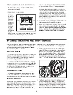
TIGHTENING THE PEDALS
If the pedals become loose, tighten the pedal shafts
into the arms of the crank. Tighten the 1/2Ó Locknuts
onto the pedal shafts (see assembly step 7 on page 6).
ADJUSTING THE CHAIN
The exercise cycle features a precision chain that must
be kept properly lubricated and adjusted. Apply a few
drops of light multi-purpose oil to the chain every three
months. If the chain is too tight, the bearings may be
damaged; if the chain is too loose, the fan may be
damaged. If the chain causes excessive noise or slips
as you pedal, check the chain in the following way:
1. Carefully pry the Access Cover (14) off the right
side shield. Reach into the access hole and press
down on the chain.
There should be no more
than 1 inch, and no less than 1/4 inch, of verti-
cal movement in the center of the chain.
If the
chain is properly adjusted, reattach the Access
Cover. If the chain needs to be adjusted, see step 2.
2. Pry the Access Cover (14) off the left side shield.
Loosen the M8 Washer Nuts (4). To tighten the
chain, turn the M6 Adjustment Nuts (8) clockwise;
to loosen the chain, turn the Adjustment Nuts coun-
terclockwise. Make sure that the fan is straight,
tighten the Fan Nuts and reattach the Access Covers.
TROUBLE-SHOOTING AND MAINTENANCE
14
8
4
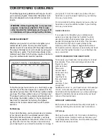
Mode indicators


