background image

20

CPU Installation

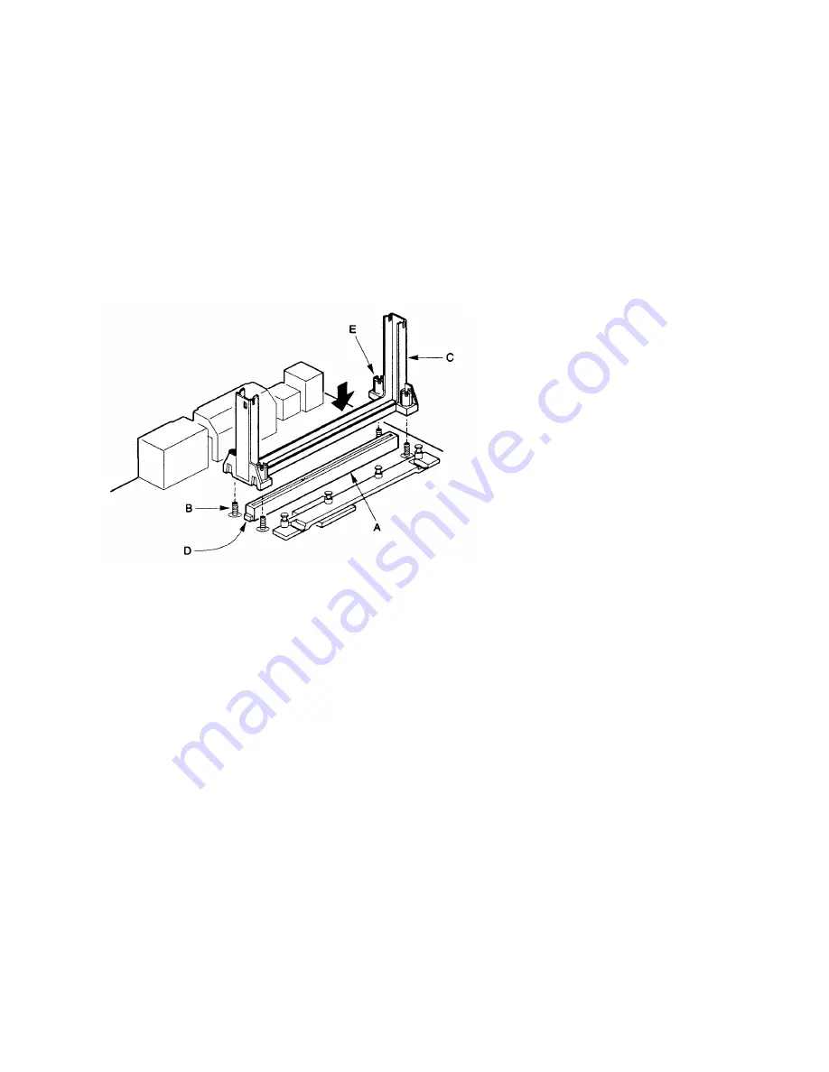
Installing the Retention Mechanism

/

NOTE

To install the retention mechanism, you need a Phillips (#2 bit) manual torque
screwdriver capable of a 6.0 in.-lb. ± 1.0 in.-lb. (0.678 N-m ± 0.113 N-m) setting. The
screwdriver also must have a shaft longer than 2 inches.

To install the retention mechanism, follow these steps:

1. Locate SIot 1 (A) and the four attachment studs (B) on the motherboard.

2. To position the mechanism (C), orient it as shown above. The tab (D) on the
connector fits into a notch in the base of the mechanism. When properly seated, the
base of the mechanism is flush with the motherboard.

CAUTION

Over tightening the captive nuts on the retention mechanism can damage the
motherboard. Tighten the captive nuts (E) to no more than 6.0 in.-Lb. ± 1.0 in.-lb.
(0.678 N-m ± 0.113 N-m).

3. Finger tighten all four captive nuts to make sure they start correctly on the threads of
the attachment studs.

4. To secure the mechanism, tighten the captive nuts with the torque screwdriver to no
more than 6.0 in.-Lb. ± 1.0 in.-lb. (0.678 N-m ± 0.113 N-m).

Summary of Contents for Kootenay

Page 1: ...Kootenay SEA440LX Motherboard User Manual Version 1 0b...

Page 2: ...ademarks or copyrights of their respective companies The product name and revision number are both printed on the board itself Manual revisions are released for each design represented by the digit be...

Page 3: ...G P 9 UNIVERSAL SERIAL BUS USB 10 IDE SUPPORT 10 REAL TIME CLOCK CMOS RAM AND BATTERY 10 SUPER I O CONTROLLER 11 BIOS SYSTEM SUPPORT 12 EXPANSION SLOTS 14 ONBOARD LAN 15 WAKE ON LAN HEADER WOL 15 FRON...

Page 4: ...RIPHERAL SETUP 41 HARDWARE MONITOR SETUP 43 AUTO DETECT HARD DISKS 44 CHANGE USER PASSWORD CHANGE SUPERVISOR PASSWORD 44 AUTO CONFIGURATION WITH OPTIMAL SETTINGS 44 AUTO CONFIGURATION WITH FAIL SAFE S...

Page 5: ...nced manageability and it s clear why the Kootenay motherboard is the ideal choice for Pentium II processor based systems Features of the Kootenay Motherboard Support for one 233 266 or 300 MHz Intel...

Page 6: ...rds Optional hardware monitor that integrates a temperature sensor fan speed headers power supply voltage monitor and support for chassis intrusion Optional Onboard LAN using the Intel 558 chipset to...

Page 7: ...7 Motherboard Layout...

Page 8: ...th and performance Single Edge Contact S E C cartridge packaging technology delivers high performance processing and bus technology to mainstream systems The cartridge includes the processor core seco...

Page 9: ...ted PCI bus mastering controller Accelerated Graphics Port A G P controller Fully synchronous PCI bus interface Data Buffering Support for system management mode SMM Intel 82371AB PCI ISA IDE Xcelerat...

Page 10: ...ies appropriate for telephony audio and other applications Error handling and fault recovery mechanisms built into the protocol IDE Support The motherboard has two independent bus mastering PCI IDE in...

Page 11: ...ace By default the I O controller interfaces are automatically configured during boot up The I O controller can also be manually configured in the Setup program Serial Ports Two 9 pin D Sub serial por...

Page 12: ...s The Infrared Data Association IrDA specification supports data transfers of up to 115 Kbaud at a distance of 1 meter BIOS System Support BIOS an acronym for Basic Input Output System stands as the f...

Page 13: ...nstalled in the system the IDE auto configuration function automatically detects and configures the drive for operation in the system This function eliminates the need to enter the Setup program after...

Page 14: ...e BIOS is stored in a flash memory device you can easily upgrade the BIOS without having to disassemble the system The flash upgrade process can be done by running a utility from a diskette or hard di...

Page 15: ...ed LED Speed On status indicates a 100 MBps connection Off status indicates a 10 MBps connection Green LED ACT Indicates there is activity on the LAN Yellow LED LNK Indicates if the LAN cable is conne...

Page 16: ...an connectors are provided Fan 1 is recommended for the CPU heatsink fan Fans 2 3 can be used for any other case or heatsink fans The pin assignment for these connectors are as follows Pin 1 Ground Pi...

Page 17: ...d an interrupt is activated to report the status LS 120 Support LS 120 MBytes Diskette technology enables users to store 120 MBytes of data on a single 3 5 Inch removable diskette LS 120 technology is...

Page 18: ...will ever change a jumper is if you need to Change the system operating speed Change the System mode Power Supply Type Clear Password NOTE A jumper is a small plastic encased conductor that slips over...

Page 19: ...on the system wait until you see video and turn the system off again Change the setting of J18 back to 1 2 the default Replace the system cover Turn on the system and change the BIOS settings accordin...

Page 20: ...chanism C orient it as shown above The tab D on the connector fits into a notch in the base of the mechanism When properly seated the base of the mechanism is flush with the motherboard CAUTION Over t...

Page 21: ...t 1 connector and the latches B on the processor lock into place The CPU Heatsink may not appear as shown in the illustrations Your heatsink will most likely be fitted with an electric fan connect the...

Page 22: ...e steps 1 Turn off all peripheral devices connected to the computer Turn off the computer 2 Remove the computer cover and locate the DIMM sockets 3 Holding the DIMM by the edges remove it from its ant...

Page 23: ...ording to manufacturer s instructions Expansion Card Installation The computer system should be switched off and the power cord removed before installing any expansion cards into the system Failure to...

Page 24: ...ere see Chapter 3 for problem descriptions and error messages Record the Setup Configuration To make sure you have a reference to the Setup values for your system we recommend you to write down the cu...

Page 25: ...Configuration with Optimal Settings Auto Configuration with Fail Safe Settings Save Settings and Exit Exit Without Saving ESC Exit Sel F2 F3 Colour F10 Save Exit Optimal Settings These settings provid...

Page 26: ...el and exit Numeric Keys 0 to 9 are used in the Virtual Keyboard and Numeric Keyboard The Setup program initially displays the Main menu screen In each screen there are options for modifying the syste...

Page 27: ...901 2099 F2 F3 Color This section describes the Setup options found on the Standard CMOS Setup menu It is used to set the time and date and to configure the disk drives If you select certain options f...

Page 28: ...he correct IDE drive parameters Click on LBA Large Mode and choose On to enable support for IDE drives with capacities greater than 528 MBYTES Click on Block Mode and choose On to support IDE drives t...

Page 29: ...MBYTES No System BIOS Cacheable Enabled Available Options Disabled IDE 0 IDE 1 IDE 2 IDE 3 FLOPPY FLOPTICAL CDROM SCSI ESC Exit Sel PgUp PgDn Modify F2 F3 Color This section describes the Setup option...

Page 30: ...Optimal and Fail Safe default settings are Read Write S M A R T for Hard Drives S M A R T Self Monitoring Analysis and Reporting Technology is a technology developed to manage the reliability of the h...

Page 31: ...er password prompt appears every time the computer is turned on If Setup is chosen the password prompt appears if WINBIOS is executed The Optimal default setting is Always Boot to OS 2 64MBYTES When u...

Page 32: ...available in the Advanced Chipset Setup menu which are used to configure the features specific to the chipset used on this motherboard If you select certain options the Setup program switches to a su...

Page 33: ...ecifies the length of the delay inserted between the RAS and CAS signals of the DRAM system memory access cycle The settings are 2 CLKs or 3 CLKs The Optimal default setting is 2 CLKs CAS Lattency Thi...

Page 34: ...options to Disabled To enable power management set Power Management APM to Enabled and set the power management timeout options as desired AGP Aperture Size This option specifies the amount of system...

Page 35: ...evice 6 Serial Port 1 Monitor Device 7 Serial Port 2 Monitor Device 8 Parallel Port Ignore Device 5 Floppy Disk Monitor Device 0 Primary master IDE Monitor Device 1 Primary slave IDE Ignore Device 2 S...

Page 36: ...ecifies the power management state that the video subsystem enters after the specified period of display inactivity has expired The settings are Disabled Standby and Suspend The default setting is Sus...

Page 37: ...ied in the value in the Full On to Standby Timeout Min option the computer enters a power saving state The settings are Monitor or Ignore The default setting is Ignore Devices 0 to 8 These options ena...

Page 38: ...y Auto PCI Slot4 IRQ Priority Auto DMA Channel 0 PnP DMA Channel 1 PnP DMA Channel 3 PnP DMA Channel 5 PnP DMA Channel 6 PnP DMA Channel 7 PnP IRQ 3 PCI PnP IRQ 4 PCI PnP IRQ 5 PCI PnP IRQ 7 PCI PnP I...

Page 39: ...ng of 64 PCI Clocks enables maximum PCI performance for this motherboard PCI VGA Palette Snoop When this option is set to Enabled multiple VGA devices operating on different buses can handle data from...

Page 40: ...rds The settings are Disabled DMA ChI DMA Ch 3 DMA Ch 5 DMA Ch 6 or DMA Ch 7 The Optimal and Fail Safe default settings are PnP IRQ3 to IRQ15 These options specify the bus that the named interrupt req...

Page 41: ...ripheral Setup menu to configure the I O support If you select certain options the Setup program switches to a subscreen for the selected option OnBoard FDC This option enables the floppy drive contro...

Page 42: ...bled The default setting for Optimal and Fail Safe is Auto Parallel Port Mode This option specifies the parallel port mode ECP Extended Capabilities Port and EPP Enhanced Parallel Port are both bi dir...

Page 43: ...F Current CPU Fan Speed 4166 RPM Current Case Fan 1 Speed 0 RPM Current Case Fan 2 Speed 0 RPM Vcore 2 800 V Vtt 1 488 V Vio 3 328 V 5 000V 5 109 V 12 000V 12 256 V 12 000V 12 238 V 5 000V 5 144 V Av...

Page 44: ...get it you must clear the BIOS Passwords see the section on Jumper Settings To enter these passwords do the following Boot your system and press DEL to enter into the BIOS setup program Select the Cha...

Page 45: ...BIOS other than the one provided by the Motherboard manufacturer will automatically have the product warranty voided Using the incorrect BIOS for upgrade might cause permanent unrecoverable damage to...

Page 46: ...edures in this chapter assume familiarity with the general terminology associated with personal computers and with the safety practices and regulatory compliance required for using and modifying elect...

Page 47: ...Parity Error Parity error in the base memory the first 64 KB block of memory 3 Base 64 KB Memory Failure Memory failure in the first 64 KB 4 Timer Not Operational A memory failure in the first 64 KB...

Page 48: ...nt than the previous value Run BIOS Setup CMOS System Options Not Set The values stored in CMOS RAM have been destroyed Run BIOS Setup CMOS Display Type Mismatch The video type in CMOS RAM does not ma...

Page 49: ...instructions Keyboard is Locked Unlock It The keyboard lock on the system is engaged The system must be unlocked to continue to boot Keyboard Interface Error There is an error in the keyboard connecto...

Page 50: ...system is booted BIT A binary digit that is the most reducible element of computer information Eight bits make one byte BOOT or BOOTSTRAP A small ROM based program which is automatically loaded when...

Page 51: ...that controls the activities performed by the computer DOS sets up an environment under which application software can load and function It is an interface between the system and application software...

Page 52: ...printer port or LPT 1 the parallel port is used to attach a printer or other peripheral using a Centronics parallel cable PARITY BIT An additional non informational bit appended to a group of 8 bits...

Reviews: