


CT2X INSTRUCTIONS
Seametrics • 253.872.0284
Page 10 seametrics.com
INSTALLATION
Installing the Sensor
• Lower the sensor to the desired depth
1
.
• Fasten the cable to the well head using a weather
proof strain-relief system. When securing a vented
cable, make sure not to pinch the cable too tightly
or the vent tube inside the cable jacket may be
sealed off.
• Take a measurement to insure the sensor is not
installed below its maximum range.
Be sure the supplied cap is securely placed on the weather-
resistant connector at the top of the cable. Do not install
such that the connector might become submerged with
changing weather conditions. The connector can withstand
incidental splashing but is not designed to be submerged.
If the sensor has the vented pressure option, install the
sensor so that the desiccant tube will not flood or lie in
water.
The sensor can be installed in any position; however, when
it leaves the factory it is tested in the vertical position.
Strapping the sensor body with tie wraps or tape will not
hurt it. If the sensor is being installed in a fluid environment
other than water, be sure to check the compatibility of the
fluid with the wetted parts of the sensor.
Desiccant Use
On sensors with a vented pressure option, a desiccant tube
prevents moisture in the air from being sucked into the
vent tube, which can cause erratic readings and sensor
damage.
The desiccant tube is filled with blue silica gel beads. A
locking barb and a hydrophobic water filter are attached to
the end of the desiccant tube. This filter prolongs the life of
the desiccant as much as three times over a desiccant tube
without the filter.
Install the sensor so that the desiccant tube and cable
connector will not flood or lie in water.
The desiccant is a bright blue color when active and dry. See
Maintenance section for care and changing of desiccant.
1 If your CT2X has the pressure option, then the maximum installation
depth depends on the range of the sensor. One (1) PSI is equal to
approximately 2.31 feet of water. If you have a 5 PSI sensor, the range
is 11.55 feet of water and the sensor should not be installed at a depth
below 11.55 feet. If the sensor is installed below its maximum range,
damage may result to the sensor and the output reading will not be
correct.
Grounding Issues
It is commonly known that when using electronic
equipment, both personnel and equipment need to be
protected from high power spikes that may be caused by
lightning, power line surges, or faulty equipment. Without
a proper grounding system, a power spike will find the
path of least resistance to earth ground—whether that
path is through sensitive electronic equipment or the
person operating the equipment. In order to ensure safety
and prevent equipment damage, a grounding system must
be used to provide a low resistance path to ground.
When using several pieces of interconnected equipment,
each of which may have its own ground, problems with
noise, signal interference, and erroneous readings may be
noted. This is caused by a condition known as a Ground
Loop. Because of natural resistance in the earth between
the grounding points, current can flow between the points,
creating an unexpected voltage difference and resulting
erroneous readings.
The single most important step in minimizing a ground loop
is to tie all equipment (sensors, dataloggers, external power
sources, and any other associated equipment) to a single
common grounding point.
Seametrics recommends
connecting the shield to ground at the connector end.
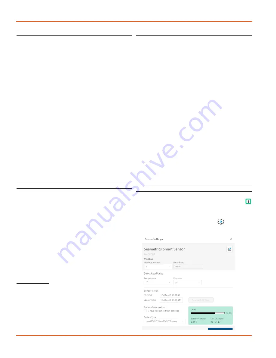
Sensor Settings
Once connected you’ll see the Sensor screen appear and
display the connected sensor(s) details. Mousing over
icons will provide tool-tips, mouse over to view sensor
firmware and serial number details.
To change general sensor settings click in the sensor
screen. This allows you to change the following:


