


8
DO NOT
use with a motor other than that built into the unit (incorrect flow pressure will distort pump accuracy).
IMPORTANT:
It is installer’s responsibility to ensure all supply pipes, fixtures and fittings are adequate for the safe flow of diesel fuel.
2. INTRODUCTION
S
elf-priming, rotary vane pump with bypass valve. Direct drive 230V motor fitted with overload protector. Volumetric, nutating disc, resettable
meter with large 3-digit display. Supplied with Model No. TP109 Automatic Delivery Nozzle and 4m of reinforced 3/4” hose. Unit is suitable for
wall, tank or pedestal installation. Flow rate 56L/min.
3. SPECIFICATION
Model no: ............................................................... TP955.V2
Current: ..............................................................................3A
Flow Rate: ................................................................. 56L/min
Pressure: .............................................................29psi(2bar)
Protection: ......................................................................... No
Speed: .....................................................................2900rpm
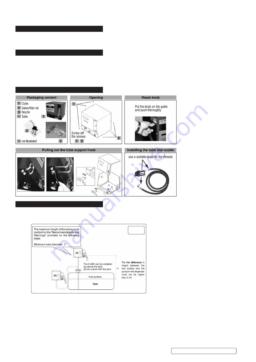
4. CONTENTS/FEATURES
5. INTSTALLATION
5.1.
The CUBE dispenser can be installed outside. Nevertheless, it is advisable to locate it under the shelter of a roof to ensure the
dispenser’s longevity and provide greater comfort during refuelling in the event of bad weather. The installation of the dispenser must
be carried out by skilled personnel and performed according to the instructions provided in this manual.
5.2.
MECHANICAL INSTALLATION fig.1
Before beginning the installation, verify that no packing material has been trapped in the tubing.
Prepare suitable stilts or fixing brackets depending on the fixing position of the unit. The tube coming from the tank must be aligned to
the threaded inlet of the pump filter which is located under the unit.
5.3.
HYDRAULIC CONNECTIONS
WARNING!
Remove the protective caps from the threads. The hydraulic connections can be made with flexible or rigid tubes with
adequate joints, as long as they are done by skilled personnel, in a workmanlike manner, with respect for the regulations in effect in
the country of installation.
5.3.1.
Maximum length of hydraulic tubing
Suction is affected by the length and diameter of the tubing and the difference in height between the tank and the height of the pump. A
back pressure must not be created greater than 0.6bar.
fig.1
Original Language Version
© Jack Sealey Limited
TP955.V2 Issue:2 (H,F) 12/10/21


