6.2.
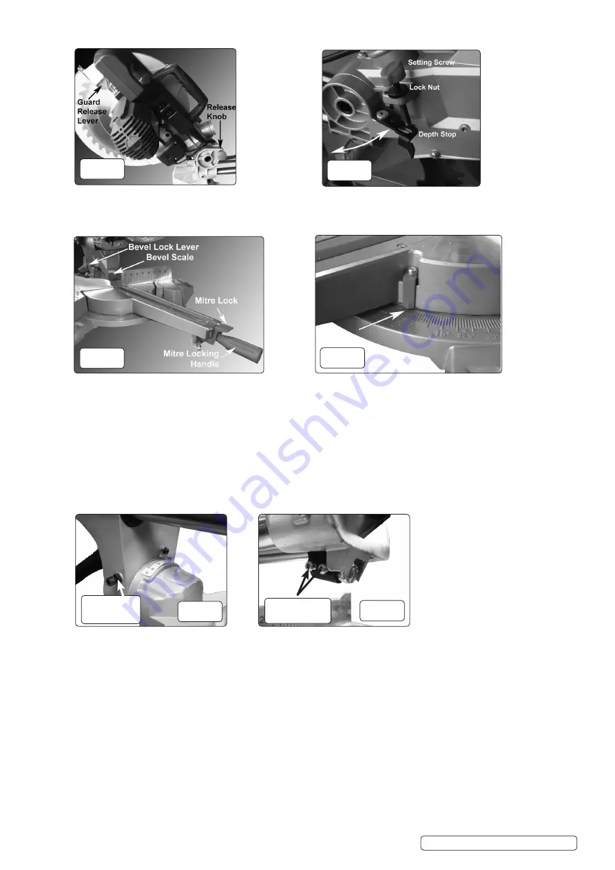
DEPTH STOP (fig.3, fig.1.17)
6.2.1.
To activate, swing the depth stop over so the setting screw rests on it when the blade is lowered (fig.3, fig.1.17).
6.2.2.
Adjust the setting screw engagement until the required cutting depth is achieved and tighten the lock nut to preserve that setting.
6.2.3.
To make a full depth cut without loosing the depth setting, push the depth stop across so the setting screw passes through it.
6.3.
MITRE ANGLE ADJUSTMENT (fig.4)
6.3.1.
The mitre angle can be set by loosening the mitre locking handle (fig.1.6, fig.4), depressing the Mitre Lock and adjusting the angle.
6.3.2.
There are detents set at: 0°, 15°, 22.5°, 31.6°, 45° and the table can be set at these angles (fig.5), applying the locking handle (fig.1.7,
fig.4) to secure it in place.
6.3.3.
The mitre angle of the table can also be set at any other angle by reading the angle from the mitre scale and locking in position by
rotating the locking handle until it is screwed in tightly and the table is fixed at the desired angle. To loosen the table, unscrew the
locking handle until it turns easily.
6.4.
VERTICAL CUTTING ANGLE
(BEVEL)
(fig.5)
6.4.1.
To adjust the vertical cutting angle, loosen the bevel lock lever (fig.1.14, fig.4) and move the head to the required angle using the
Bevel Scale (fig.1.13, fig.4) for guidance.
6.4.2.
To check the vertical angle setting, lower and lock the blade as in section 6.1. Ensure that the pointer is set to zero.
6.4.3.
Place a square (not supplied) against the blade to determine if the blade is perpendicular to the table.
6.4.4.
If not perpendicular, tilt the head over to reveal the bevel angle stop adjusters (fig.6, fig.1.12).
6.4.5.
Loosen the adjuster lock nuts and, using a hex key, either screw the adjusters in or out in order to bring the blade square.
6.4.6.
When the blade is true, tighten the lock nuts.
6.4.7.
If necessary, loosen the screw securing the pointer and move the pointer to 0°. Tighten the securing screw after moving.
6.5.
SIDE SUPPORTS
6.5.1.
Side Supports (fig.1.19) are provided for both sides of the table. These must be locked in the required position to support long work.
6.5.2.
Each support is provided with a retractable stop.
6.6.
CLAMP ASSEMBLY
6.6.1.
The Clamp Assembly (fig.1.11) may be fitted to either side of the table by fitting into the holder and secured using the thumb wheels.
6.6.2.
Screw the clamp down onto the work whenever possible to secure before cutting.
6.7.
LASER GUIDE
6.7.1.
The laser cutting guide may be switched on with push button switch (fig.1.2). If the laser beam is showing off centre, turn laser on and
use the two screws holding the laser unit in place to realign it with the centre line of the kerf plate (fig.7).
8
DO NOT
look into the laser light.
6.8.
FENCE GUIDE RAILS
6.8.1.
The guide rail travel is provided in two stages. If a limited travel is required, either stage may be locked by tightening the sliding
lock (fig.1.11).
6.8.2.
For cutting small section work, both rails may be locked so the saw head does not move to and fro.
S
MS216.V2 Issue:1 18/03/21
Original Language Version
© Jack Sealey Limited
fig.2
fig.3
fig.4
fig.5
fig.6
B
evel Angle
Adjuster
(both sides)
fig.7
Laser alignment
Screws


