

G2000i.V2 | issue 1 05/09/16
Original Language Version
© Jack sealey limited
7. MaIntenance
WarnIng!
stop the engine before servicing. Put the engine on a level surface and remove spark plug cap.
in order to keep the engine in good working condition, it must be serviced.
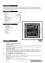
items
frequency
each time
f
irst month or first
20hrs of operation
every 3 months
or every 50hrs of
operation
every Year or every
100hrs of operation
engine oil
c
heck-Refill
9
replace
9
9
reduction gear oil
(if equipped)
oil level check
9
replace
9
9
Air filter element
check
9
clean
9
replace
9
deposit cup
(if equipped)
clean
9
spark Plug
check-Adjust
9
*
spark Arrester
clean
9
idling (if equipped) **
check-Adjust
9
Valve clearance **
check-Adjust
9
f
uel tank/filter
clean
9
fuel line
check
every 2 Years (change if necessary)
cylinder head piston
clean carbon **
< 225cc every 125hrs
,
≥
225cc every 250hrs.
* these items should be replaced if required.
**the repair work should be carried out by authorized stockists.
if the engine frequently works under high temperature or heavy load, change the oil every 25hrs.
i
f the engine works in a dusty atmosphere clean the air filter element every 10hrs. If necessary change the air filter element every 25hrs.
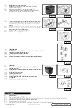
7.1.
spark plug Inspection
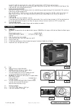
7.1.1.
remove cap in outer case and the spark plug cap. insert spark plug socket through external case
turn counter clockwise to remove spark plug.
7.1.2.
check for discolouration and remove the carbon. the porcelain insulator around the centre electrode
of the spark plug should be a medium to light tan colour.
7.1.3.
Check the spark plug gap fig.15. this should be measured with a thickness gauge.
7.1.4.
install the spark plug.
7.1.5.
install the spark plug cap and the spark plug cover.
standard spark Plug................ e6tc/e6rtc
spark Plug Gap.............................0.6-0.7mm.
spark Plug torque...........................20.0 nm
7.2.
carburettor adjustment
Adjusting the carburettor should be left to an authorised stockist with the professional knowledge,
specialised data and equipment to adjust to the correct settings.
7.3.
engine oil replacement
7.3.1.
Place the generator on a level surface and warm up the engine for several minutes.
7.3.2.
switch off engine, switch fuel knob to “off” and switch fuel tank cap air vent to “off”. remove
spark plug cap.
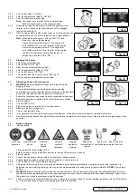
7.3.3.
Remove the two screws fig.16.1 in the side panel and remove panel fig.16.2.
7.3.4. Remove the oil filler cap.
7.3.5.
Place an oil pan under the engine. tilt the generator to drain the oil completely.
7.3.6.
Place the generator back on a level surface.
Do not
tilt the generator when adding engine oil. this
could result in over filling and damage to the engine.
7.3.7.
Add engine oil to the upper level. (see section 6.1)
7.3.8.
Wipe the cover clean and ensure no foreign material enters the crankcase.
7.3.9.
install the cover and tighten the screws.
7.4.
air filter
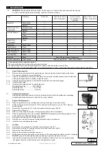
7.4.1.
Remove the two screws fig.16.1 and then remove the cover fig.16.2.
7.4.2.
Remove the screw fig.16.3 and then remove the air filter case cover fig.16.4.
7.4.3.
Remove the foam element fig.17.5
7.4.4.
Wash the foam element in detergent and dry it.
7.4.5.
oil the foam element and squeeze out the excess oil. the foam element should be wet but not dripping.
8
Do not
wring out the foam element when squeezing it, as this could cause it to tear.
7.4.6.
Insert the foam element into the air filter case. Install the air filter case cover in its original position
and tighten the screw. install the side cover and tighten the screws.
fig.16
fig.17
fig.15