
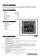

G2000i.V2 | issue 1 05/09/16
Original Language Version
© Jack sealey limited
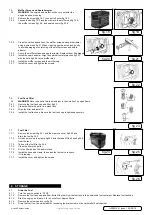
6.3.3.
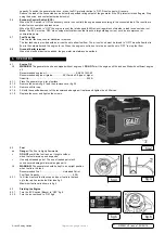
Turn the fuel Knob to “ON” fig.7.
6.3.4.
Turn the engine switch (Red) to “ON” fig.8.
6.3.5.
Turn the choke knob fully out fig.9.
note
:- the choke is not required to start a warm engine.
Push the choke knob in to the original position.
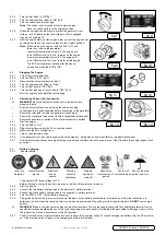
6.3.6.
Grasp the carrying handle firmly to prevent the generator from
falling over. Pull slowly on the recoil starter until it is engaged,
then pull it briskly fig.10.
6.3.7.
After the engine starts, let the engine warm up until the engine does
not stop when the choke knob is retuned to the original position.
note
:- When starting the engine , with the ecs “on” and
there is no load on the generator:
in ambient temperature below 0°c the engine will
run at 4500rev/min. for 5 min. to warm up the engine.
in ambient temperature below 5°c the engine will
run at 4500rev/min. for 3 min. to warm up the engine.
the ecs unit operates normally after the above
time period, while the ecs is “on”.
6.4.
stopping the engine
6.4.1.
turn off any electric devices.
6.4.2. Turn the ECS to “OFF” fig.11.
6.4.3.
Disconnect any electrical devices fig.12.
6.4.4.
turn the engine switch (red) to “stop”.
6.4.5.
Turn the fuel knob to “OFF”fig.13.
6.4.6.
Turn the fuel tank cap air vent knob to “OFF” fig.14
after the engine has completely cooled down.
6.5.
alternating current (ac) connection
WarnIng!
Be sure any electric devices are turned off before
plugging them in.
9
ensure all electrical devices including the cables and plug
connections are in good condition before connecting to the generator.
9
ensure the total load is within the generator rated output.
9
ensure the receptacle load current is within receptacle rated current.
9
ensure the generator is earthed, if the electrical device is earthed.
6.5.1.
start the engine.
6.5.2.
turn the ecs to “on”.
6.5.3.
Plug electrical device into the Ac connection socket.
6.5.4.
make sure the Ac pilot light is on.
6.5.5.
turn on the electrical device.
6.5.6.
if the generator is to be used to supply medical equipment , obtain advice from manufacture / medical professional.
6.5.7.
some electrical appliances have high starting currents and therefore can not be used, even if they lie within the supply ranges of the
generator.
6.6.
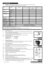
Battery charging
6.6.1. General safety
the generator dc rated voltage is 12V.
Before starting to charge the battery, make sure that the dc protector is turned on.
6.6.2.
start the engine.
6.6.3.
connect the red battery charger lead to the positive (+) battery terminal.
6.6.4.
connect the black battery charger lead to the negative (-) battery terminal.
6.6.5.
turn the ecs to “off” to start battery charging.
6.6.6.
charge the battery using the correct procedure laid down by the battery manufacturer’s instructions. follow the instructions to
determine the end of battery charging, this may include measurements of specific gravity at regular intervals.
Do not
over charge
battery.
WarnIng!
“modern vehicles contain extensive electronic systems. You are required to check with the vehicle manufacturer, for any
specific instructions regarding the use of this type of equipment on each vehicle. No liability will be accepted for damage / injury, where
this product is not used in accordance with all instructions.”
6.6.7.
the dc protector turns off automatically if current is above the generator rating. to restart charging the battery, turn the dc protector
on. if the protector turns off again, stop charging the battery immediately.
fig.7
fig.9
fig.11
fig.8
fig.10
fig.12
fig.14
fig.13
electrical
shock
hazard
Wear eye
protection
Wear protective
gloves
Warning
corrosive
substance
Warning:
explosive
material
Keep away
from sources of
ignition
use in well
ventilated areas
Keep in dry area
protect from rain