


5.3. Accurate Measurement
5.3.1. Follow procedure 5.1.1 through 5.1.4.
5.3.2. The bore or gap machined finish must be clean with surface texture 3.2µm to 6.4µm or better than for fiducial indication.
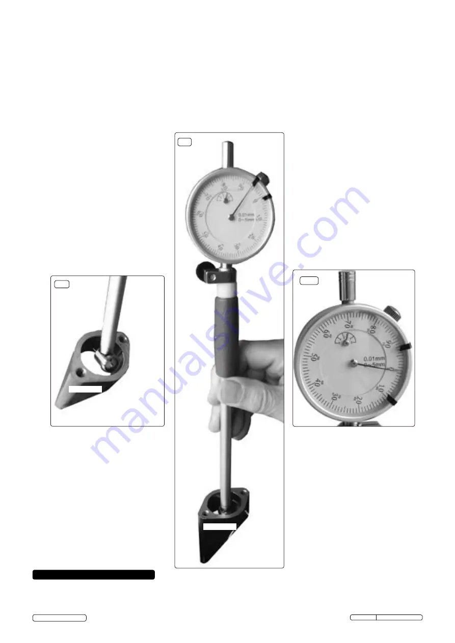
5.3.3. offer the anvil end into the bore at an angle (fig.8) with the anvil tip entering just ahead of the sprung loaded self centering guide. rock
the dial gauge tube to the horizontal position (fig.9) and beyond, observing the pointer sweep. The three point location offered by the
spring loaded self centering guide and the anvil tip will align the head.
5.3.4. rotate the bezel such that the "0" [zero] aligns with the largest sweep position of the pointer (fig.10). It is essential to observe the total
sweep of the dial pointer using the small dial. remember from the initial setting the pointer had rotated one full cycle. Mark the position
on the component of where the measurement was taken, if required.
5.3.5. With a micrometer, measure across the anvil and the nib (fig.11), rotate the barrel of the micrometer until the dial pointer aligns with the
same "0" [zero] as the measured bore. Take the reading from the micrometer and record.
5.3.6. With the bore dial gauge now set, the bore can now be measured for taper and ovality by reference back to the initial datum "0" [zero]
reading and counting the 0.01mm divisions between datum and new. note! the larger the deflection the smaller the bore.
fig.8
"offer the anvil end into the bore slightly tilted...."
"rotate the bezel such that the
"0" [zero] aligns....."
6. MAINTENANCE
6.1.
Keep all components dry and clean with a soft micro fibre cloth.
6.2.
return all items to the presentation case after use.
6.3.
store indoors in a temperature controlled dry environment, circa 21°C.
6.4.
This is a precision instrument intended for use by engineers and engineering inspectors, keep out of reach of children.
Component
dBG508 Issue: 1 - 19/06/15
Original Language Version
© Jack sealey limited
Component
fig.9
fig.10
"rock the dial
gauge tube to
the upright
position....."


