SeaLevel PC-ACB.MP User Manual Download Page 21


21 

 
         © Sealevel Systems, Inc. 

3612 Manual   |  SL9115  9/2021 


Warranty 

Sealevel's  commitment  to  providing  the  best  I/O  solutions  is  reflected  in  the  Lifetime  Warranty  that  is 
standard on all Sealevel manufactured I/O products. We are able to offer this warranty due to our control 
of manufacturing quality and the historically high reliability of our products in the field. Sealevel products 
are designed and manufactured at its Liberty, South Carolina facility, allowing direct control over product 
development, production, burn-in and testing. Sealevel achieved ISO-9001:2015 certification in 2018. 

Warranty Policy 

Sealevel  Systems, Inc.  (hereafter "Sealevel") warrants that the  Product shall  conform to and perform in 
accordance  with  published  technical  specifications  and  shall  be  free  of  defects  in  materials  and 
workmanship for the warranty period. In the event of failure, Sealevel will repair or replace the product at 
Sealevel's sole discretion. Failures resulting from misapplication or misuse of the Product, failure to adhere 
to any specifications or instructions, or failure resulting from neglect, abuse, accidents, or acts of nature 
are not covered under this warranty.  

Warranty service may be obtained by delivering the Product to Sealevel and providing proof of purchase. 
Customer agrees to ensure the Product or assume the risk of loss or damage in transit, to prepay shipping 
charges  to  Sealevel,  and  to  use  the  original  shipping  container  or  equivalent.  Warranty  is  valid  only  for 
original purchaser and is not transferable.  

This  warranty  applies  to  Sealevel  manufactured  Product.  Product  purchased  through  Sealevel  but 
manufactured by a third party will retain the original manufacturer's warranty.  

Non-Warranty Repair/Retest


Products returned due to damage or misuse and Products retested with no problem found are subject to 
repair/retest charges. A purchase order or credit card number and authorization must be provided in order 
to obtain an RMA (Return Merchandise Authorization) number prior to returning Product.  

How to obtain an RMA (Return Merchandise Authorization) 

If you need to return a product for warranty or non-warranty repair, you must first obtain an RMA number. 
Please contact Sealevel Systems, Inc. Technical Support for assistance: 

Available  

Monday 

 Friday, 8:00AM to 5:00PM EST 

Phone   

864-843-4343  

Email 


[email protected]


Trademarks 

Sealevel Systems, Incorporated acknowledges that all trademarks referenced in this manual are the service 
mark, trademark, or registered trademark of the respective company.  

Summary of Contents for PC-ACB.MP

Page 1: ...1 Sealevel Systems Inc 3612 Manual SL9115 9 2021 PC ACB MP User Manual 3612 ...

Page 2: ...ts CONTENTS 2 INTRODUCTION 3 BEFORE YOU GET STARTED 4 INSTALLATION 5 TECHNICAL DESCRIPTION 7 SPECIFICATIONS 15 APPENDIX A TROUBLESHOOTING 16 APPENDIX B HOW TO GET ASSISTANCE 17 APPENDIX C ELECTRICAL INTERFACE 18 APPENDIX D COMPLIANCE NOTICES 20 WARRANTY 21 ...

Page 3: ...tor standard for memory cards In 1989 PCMCIA adopted the JEIDA 68 pin standard and worked with JEIDA on further developments As the notebook market grew the need for a standard I O bus was seen The PCMCIA groups saw an opportunity to meet this need with an expanded version of the 68 pin interface Further development occurred and within one year release 2 0 of the standard was completed Release 2 0...

Page 4: ...ying Case Jewel Case Advisory Conventions Warning The highest level of importance used to stress a condition where damage could result to the product or the user could suffer serious injury Important The middle level of importance used to highlight information that might not seem obvious or a situation that could cause the product to fail Note The lowest level of importance used to provide backgro...

Page 5: ...rovide adequate support for most applications Connecting the PC ACB MP to the computer requires no special technical skills In fact it is usually done in as simple as two steps 1 Follow the directions below which are given for your operating system in the Software Installation The SeaMAC synchronous serial driver must be installed prior to the hardware being installed 2 Simply slide the card into ...

Page 6: ...sync and RAW protocols are supported Please contact Sealevel Systems Inc Technical Support to discuss your specific requirements 864 843 4343 Our technical support is free and available from 8 00 AM to 5 00 PM Eastern Time Monday through Friday For email support contact support sealevel com Installation is complete Optional Items The PC ACB MP has several cabling options available All optional ite...

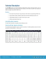
Page 7: ... V 35 Programmable options for Transmit clock as input or output Software programmable baud rate Internal Baud Rate Generator The baud rate of the ESCC is programmed under software control Control and Status Registers Definition The control and status registers occupy 16 consecutive locations The following tables provide a functional description of the bit positions X do not care Base Mode D7 D6 D...

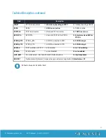
Page 8: ... RXCOPTA 1 Selects SCC PCLK for RTXCA 0 Selects received RXC for RTXCA SYNCA_RTS SYNCA _RTS 1 SYNCA connected to RTS 0 SYNCA is high SYNCA_CTS SYNCA_CTS 1 SYNCA connected to CTS 0 SYNCA is high 485CLK TSET switches with TXD 1 clk switches 0 no CLK switching ECHOA ECHO enable 1 echo disabled 0 echo enabled AM0 AM3 I O mode select See table for valid interface options 0 High Impedance SD0 SD7 Option...

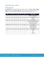
Page 9: ...tion There is line termination on RXD RXC and TXC in the following modes RS 530 RS 530A RS 485T and V 35 HEX M3 M2 M1 M0 Interface Mode 0 0 0 0 0 All signals are high impedance 1 0 0 0 1 not supported 2 0 0 1 0 RS 232 3 0 0 1 1 not supported 4 0 1 0 0 RS 485T with 120 ohm termination 5 0 1 0 1 RS 485 without termination 6 7 8 9 0 1 1 0 not supported A 1 0 1 0 single ended loop back B 1 0 1 1 diffe...

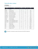
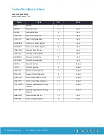
Page 10: ...er Detect 8 Input TM Test Mode 25 Input TXC Transmit Clock 15 Input RXC Receive Clock 17 Input TSET Transmit Signal Element Timing 24 Output DTR Data Terminal Ready 20 Output TD Transmit Data 2 Output RTS Request To Send 4 Output Please terminate any control signals that are not going to be used The most common way to do this is connect RTS to CTS and RI Also connect DCD to DTR and DSR Terminating...

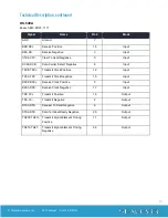
Page 11: ... Input RXCB RXC Receive Clock Positive 9 X Input RXCA RXC Receive Clock Negative 17 V Input TDB TX Transmit Positive 14 S Output TDA TX Transmit Negative 2 P Output TSETB TSET Transmit Signal Element Timing 11 W Output TSETA TSET Transmit Signal Element Timing 24 U Output CTS Clear To Send 5 D Input DSR Data Set Ready 6 E Input DCD Data Carrier Detect 8 F Input DTR Data Terminal Ready 20 H Output ...

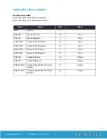
Page 12: ...it Clock Positive 12 Input TXCA TXC Transmit Clock Negative 15 Input RXCB RXC Receive Clock Positive 9 Input RXCA RXC Receive Clock Negative 17 Input TDB TX Transmit Positive 14 Output TDA TX Transmit Negative 2 Output RTSB RTS Request To Send Positive 19 Output RTSA RTS Request To Send Negative 4 Output DTRB DTR Data Terminal Ready Positive 23 Output DTRA DTR Data Terminal Ready Negative 20 Outpu...

Page 13: ... Detect Negative 8 Input TXCB TXC Transmit Clock Positive 12 Input TXCA TXC Transmit Clock Negative 15 Input RXCB RXC Receive Clock Positive 9 Input RXCA RXC Receive Clock Negative 17 Input TDB TX Transmit Positive 14 Output TDA TX Transmit Negative 2 Output RTSA RTS Request To Send Negative 4 Output DTRA DTR Data Terminal Ready Negative 20 Output TSETB TSET Transmit Signal Element Timing Positive...

Page 14: ...RX Receive Positive 16 Input RDA RX Receive Negative 3 Input TXCB TXC Transmit Clock Positive 12 Input TXCA TXC Transmit Clock Negative 15 Input RXCB RXC Receive Clock Positive 9 Input RXCA RXC Receive Clock Negative 17 Input TDB TX Transmit Positive 14 Output TDA TX Transmit Negative 2 Output TSETB TSET Transmit Signal Element Timing Positive 11 Output TSETA TSET Transmit Signal Element Timing Ne...

Page 15: ...midity Range 10 to 90 R H Non Condensing 10 to 90 R H Non Condensing Manufacturing All Sealevel Systems Printed Circuit boards are built to UL 94V0 rating and are 100 electrically tested These printed circuit boards are solder mask over bare copper or solder mask over tin nickel Power Consumption Supply Line 5 VDC Rating 170 mA Mean Time Between Failures MTBF Greater than 150 000 hours Calculated ...

Page 16: ... in your system This includes your on board serial ports controller cards sound cards etc The I O addresses used by these adapters as well as the IRQ if any should be identified 2 Make sure the Sealevel Systems adapter is securely installed in a PCMCIA slot 3 Use the supplied Sealevel Software and this User Manual to verify that the Sealevel Systems adapter is configured correctly This software co...

Page 17: ...vides an FAQ section on its web site Please refer to this to answer many common questions This section can be found at http www sealevel com faq asp Sealevel Systems maintains a web page on the Internet Our home page address is www sealevel com The latest software updates and newest manuals are available via our web site Technical support is available Monday to Friday from 8 00 a m to 5 00 p m eas...

Page 18: ...tes a binary 1 mark The RS 232 and the EIA TIA 574 specification defines two type of interface circuits Data Terminal Equipment DTE and Data Circuit Terminating Equipment DCE The Sealevel Systems adapter is a DTE interface RS 422 The RS 422 specification defines the electrical characteristics of balanced voltage digital interface circuits RS 422 is a differential interface that defines voltage lev...

Page 19: ... signal levels are met and the pin out for the DB 25 connector is specified The EIA Electronic Industry Association created the RS 530 specification to detail the pin out and define a full set of modem control signals that can be used for regulating flow control and line status The major difference between RS 530 and RS 530A lies in the modem control interface signals In RS 530 all signals are dif...

Page 20: ...d to correct the interference at the user s expense EMC Directive Statement Products bearing the CE Label fulfill the requirements of the EMC directive 89 336 EEC and of the low voltage directive 73 23 EEC issued by the European Commission To obey these directives the following European standards must be met EN55022 Class A Limits and methods of measurement of radio interference characteristics of...

Page 21: ...nty Warranty service may be obtained by delivering the Product to Sealevel and providing proof of purchase Customer agrees to ensure the Product or assume the risk of loss or damage in transit to prepay shipping charges to Sealevel and to use the original shipping container or equivalent Warranty is valid only for original purchaser and is not transferable This warranty applies to Sealevel manufac...

Reviews: