


11
© Sealevel Systems, Inc.
3612 Manual | SL9115 9/2021
Technical Description, continued
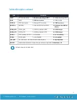
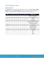
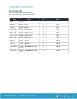
V.35 Signals
Base+5, M3-M0=E, 1110
Signal
Name
DB-25
V.35
Mode
GND
Ground
7
B
RDB RX+
Receive Positive
16
T
Input
RDA RX-
Receive Negative
3
R
Input
TXCB TXC+
Transmit Clock Positive
12
AA
Input
TXCA TXC-
Transmit Clock Negative
15
Y
Input
RXCB RXC+
Receive Clock Positive
9
X
Input
RXCA RXC-
Receive Clock Negative
17
V
Input
TDB TX+
Transmit Positive
14
S
Output
TDA TX-
Transmit Negative
2
P
Output
TSETB TSET+
Transmit Signal Element
11
W
Output
TSETA TSET-
Transmit Signal Element Timing -
24
U
Output
CTS
Clear To Send
5
D
Input *
DSR
Data Set Ready
6
E
Input *
DCD
Data Carrier Detect
8
F
Input *
DTR
Data Terminal Ready
20
H
Output *
RTS
Request To Send
4
C
Output *
All modem control signals are single ended (un-balanced) with RS-232 signal levels.


