


Aqua Whisper DX Modular 450-1800
Page 3-23
Pre-installa
tion
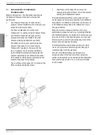
hose. Also used for a manual fresh water flush if
the Automatic Fresh Water Flush System is not
installed. The Rinse Clean Valves are available on
single valve mounting plates or on double valve
mounting plate.
7.
Rinse Clean Outlet Valve *** used in conjunction
with and identical to the Rinse Clean Inlet Valve
simplifies the storage and cleaning procedures by
allowing the operator to turn a valve rather than
disconnect a hose.
ELECTRONIC SECTION
The Electronic Section measures water quality, controls
the direction of Product Water flow, Starts and Stops the
pumps, and contains the central electrical connection
point of the system. It also ensures only potable Product
Water passes into the Product Water Storage Tank.
1.
System Touch Panel is where all system functions
are accessed by touching the user friendly
intuitive screen and where all operating conditions
are monitored.
2.
Electrical Control Box contains all electrical and
electronic components that control the system.
3.
Remote Control Touch Panel *** allows for remote
control, operation, and monitoring of the system.
4.
Soft Start *** The soft start, used only in AC Single
Phase systems, reduces the initial startup amperes
required to start the High Pressure Pump Motor
and in turn allows a smaller sized KW generator to
start the system. Starting amperage is reduced by
40% with the Soft Start installed.
Not Numbered:
Fresh Water Tank Low Level Switch ** owner/installer
supplied provides an optional feature to the System
Control Logic that works in conjunction with the
Automatic Fresh Water Flush option.
When installed and connected to the Main Printed Circuit
Board, the Fresh Water Tank Low Level Switch must be
connected as a N.O. (Normally Open) 1PST (One Pole
Single Throw) switch.
When the Fresh Water Tank is empty the switch is Open.
As water rises a few inches in the tank the switch Closes.
This informs the System Control Logic that there is
sufficient Fresh Water to perform the Automatic Fresh
Water Flush Cycle.
2.
Fresh Water Pressure Pump** delivers fresh water
throughout the boat, or home. In order to provide
the required flow of water to the System during
the Fresh Water Flush cycle, this pump must
deliver up to 1 U.S. Gallons (3.8 Liters) Per Minute
at 25 to 60 PSI (172 to 414 kPa).
3.
Air Entrainment Tank** (accumulator) is sometimes
installed into the boat or home’s fresh water line to
eliminate pulsations from and reduce demand on
the Fresh Water Pressure Pump. This tank stores
pressurized fresh water for delivery to the boat or
home’s fresh water piping.
FRESH WATER FLUSH SECTION
The Fresh Water Flush Section includes a Carbon
Filter and an Automatic Motor Actuated Ball Valve that
automatically flushes the system with fresh water. This
process is automatic at each shut down of the system
and repeats automatically every preset number of days.
Fresh Water Flushing replaces the seawater in the
system with less corrosive fresh water, and this also
reduces the biological growth and subsequent decay that
naturally occur if the sea water is not flushed from the
system with fresh water.
1.
Fresh Water Flush 2-way solenoid valve
***automatically actuates at system shut down
and every preset number of days there after to
flush the system with fresh water.
2.
Fresh Water Flush Check Valve *** prevents feed
water from entering the fresh water line.
3.
Fresh Water Flush Charcoal Filter *** removes
chlorine, if present, in the fresh water prior to
flowing through the R.O. Membrane Element.
4.
Fresh Water Flush Check Valve *** routs the fresh
water through the system.
5.
Cleaning Bucket ** can be any non ferrous
container capable of holding at least 10 U.S.
Gallons (37.8 Liters) of water. This container is
used during the R.O. Membrane Element cleaning,
storing, or winterizing process.
6.
Rinse Clean Inlet Valve *** These Optional Valves
are mounted separately on singular individual
plates or together on a double plate.
The Rinse Clean Inlet Valve is used in conjunction
with the Rinse Clean Outlet Valve simplifies the
storage and cleaning procedures by allowing the
operator to turn a valve rather than disconnect a
Summary of Contents for Aqua Whisper DX 1400-2
Page 2: ......
Page 3: ...Aqua Whisper DX Modular 450 1800 Owner s Manual...
Page 4: ......
Page 11: ...Introduction Aqua Whisper DX Modular 450 1800 Section 1 INTRODUCTION...
Page 12: ...Introduction...
Page 15: ...Description Aqua Whisper DX Modular 450 1800 Section 2 SYSTEM DESCRIPTION...
Page 16: ...Description...
Page 21: ...Aqua Whisper DX Modular 450 1800 Page 2 5 Description COMPLIANCE CERTIFICATES...
Page 23: ...Aqua Whisper DX Modular 450 1800 Page 2 7 Description...
Page 25: ...Aqua Whisper DX Modular 450 1800 Page 2 9 Description...
Page 30: ...Aqua Whisper DX Modular 450 1800 Page 2 14 Description OPTIONAL ACCESSORIES...
Page 38: ...Aqua Whisper DX Modular 450 1800 Page 2 22 Description This page is intentionally left blank...
Page 39: ...Aqua Whisper DX Compact 450 1800 Section 3 PRE INSTALLATION NOTES Pre installation...
Page 40: ...Pre installation...
Page 56: ...Aqua Whisper DX Modular 450 1800 Page 3 16 Pre installation...
Page 57: ...Aqua Whisper DX Modular 450 1800 Page 3 17 Pre installation...
Page 65: ...Aqua Matic Compact 450 1800 Section 4 ELECTRICAL INFORMATION Electrical...
Page 66: ...Electrical...
Page 75: ...Aqua Whisper DX Modular 450 1800 Page 4 9 Electrical Electrical Motor Wiring Three Phase...
Page 80: ...Electrical...
Page 81: ...Installation Aqua Whisper DX Modular 450 1800 Section 5 INSTALLATION REQUIREMENTS...
Page 82: ...Installation...
Page 94: ...Aqua Whisper DX Modular 450 1800 Page 5 12 Installation...
Page 95: ...Commissioning Aqua Whisper DX Modular 450 1800 Section 6 COMMISSIONING...
Page 96: ...Commissioning...
Page 106: ...Aqua Whisper DX Modular 450 1800 Page 6 10 Commissioning...
Page 107: ...Operation Aqua Whisper DX Modular 450 1800 Section 7 OPERATION...
Page 108: ...Operation...
Page 120: ...Aqua Whisper DX Modular 450 1800 Page 7 12 Operation...
Page 122: ...Aqua Whisper DX Modular 450 1800 Page 7 14 Operation...
Page 123: ...Aqua Whisper DX Compact 450 1800 Section 8 MAINTENANCE AND REPAIR Maintenance...
Page 124: ...Maintenance...
Page 145: ...Troubelshooting Troubelshooting Aqua Whisper DX Modular 450 1800 Section 9 TROUBLESHOOTING...
Page 146: ...Troubelshooting...
Page 167: ...Parts View Aqua Whisper DX Modular 450 1800 Section 10 EXPLODED PARTS VIEW...
Page 168: ...Parts View...
Page 183: ...Aqua Whisper DX Modular 450 1800 Page 10 15 Parts View...
Page 191: ...Aqua Whisper DX Modular 450 1800 Page 10 23 Parts View...
Page 217: ...Sheet 11 3 Aqua Whisper DX Electrical Wiring Diagram 110 120 VAC 50 60 HZ Single Phase...
Page 219: ...Sheet 11 5 Aqua Whisper DX Electrical Wiring Diagram 208 240 VAC 50 60 HZ Single Phase...
Page 221: ...Sheet 11 7 Aqua Whisper DX Electrical Wiring Diagram 200 240 VAC 50 60 HZ Three Phase...
Page 223: ...Sheet 11 9 Aqua Whisper DX Electrical Wiring Diagram 380 460 VAC 50 60 HZ Three Phase...
Page 225: ......


