background image

20

Installing Dura-labels

Dura-label RF tags have a diminutive form factor that allows them to be
installed in areas that cannot accommodate conventional RF tags.
In addition, Dura-labels can communicate with the scanner without having
to be in the line-of-sight.  This unique combination provides tremendous
flexibility when determining a location for placing tags.

In textile applications, for example, tags can be inserted into the front tail
of a shirt or the waistline of pants using a heat seal patch and a heat
press.  Because this system does not require line-of-sight scanning, the
tag does not have to be visible to the scanner.

When considering locations for installing tags, make sure they are within
20 inches of the scanner antenna for at least 3 milliseconds so data (16-
bit word) can be read from the tag.  Avoid locations where metal or
water is present because radio-frequency communication does not
penetrate metal and is absorbed by water.

DRAFT

Summary of Contents for INSTASCAN S512-C

Page 1: ...INSTASCAN SCANNER MODEL S512 C Operations Manual SCS Corporation 10905 Technology Place San Diego CA 92127 Phone 858 485 9196 Fax 858 485 0561 www scs corp com info scs corp com DRAFT...

Page 2: ...e d i n t h i s O p e r a t i o n s M a n u a l S C S m a k e s n o c o m m i t m e n t t o u p d a t e o r k e e p c u r r e n t t h e i n f o r m a t i o n i n t h i s O p e r a t i o n s M a n u a...

Page 3: ...s 1 3 C o n n e c t i n g t o a P C S e r i a l P o r t o r R S 2 3 2 1 4 C o n n e c t i n g t o a n A C O u t l e t 1 5 T e s t i n g t h e S c a n n e r S e t u p 1 6 A l i g n i n g t h e A n t e...

Page 4: ...r S p e c i f i c a t i o n s 3 4 C h a p t e r 6 D B 2 5 C o n n e c t o r F u n c t i o n 3 6 P i n A s s i g n m e n t s 3 7 R e c e i v e A n t e n n a S e l e c t L i n e s 3 7 T r a n s m i t A...

Page 5: ...information to and reads information from RF tags using a read write head antenna The scanner conforms to FCC Part 15 specifications and can operate with one or two externally connected antennas Dura...

Page 6: ...ne contaminants such as dust dirt oil and mist as well as label damage and objects residing outside the line of sight result in inefficient and erroneous results The SCS Interactive Identification Sys...

Page 7: ...ags in the scan field without misidentification or identifying the same tag multiple times Its technology also uses a robust protocol that maintains a uniform per tag scan time regardless of the numbe...

Page 8: ...into its own connector on the rear panel of the scanner Warning RF cable connections should be tightened to 8 inch pounds Over tightened RF cables damage the ports on the antennas and the S512 C Loos...

Page 9: ...m requirements 486 processor or better Compatible screen and keyboard 9 pin RS 232 port Windows 95 or 98 16 MB of RAM 32 MB recommended The applications you use to interface with this system may have...

Page 10: ...ovides information on radio frequency RF communications Chapter 4 Troubleshooting describes how to identify resolve and avoid problems when using the scanner and tag This chapter also contains Custome...

Page 11: ...Installation Installation Installation T his chapter provides instructions for installing the S512 C scanner and tag s LEDs and Connectors The scanner provides the connectors and LEDs described in th...

Page 12: ...wo coaxial connectors for connecting external antennas Either one or two antennas can be connected to the scanner For instructions on connecting antennas to the scanner refer to page 12 Figure 4 S512...

Page 13: ...om external power supply Activity Error Yellow Flicker scanner detects tag information Constant flickering with no tag in the scanning field a Noisy environment or possible interference resulting in d...

Page 14: ...tandard DC power receptacle The power supply provided with the scanner should be plugged into this connector and into the wall outlet For more information refer to Connecting to an AC Outlet on page 1...

Page 15: ...ear desired antenna locations 2 Connect external antennas see page 12 3 Place the antenna for optimum read write operation see page 13 4 Connect the scanner to PC serial port or RS 232 see page 14 5 C...

Page 16: ...5 If using one antenna it should be connected to antenna port 1 and antenna port 2 should be terminated with a 50 ohm load Figure 5 Connecting External Antennas Warning RF cable connections should be...

Page 17: ...e In addi tion make sure there are no metallic surfaces between or in relative proximity to the scanner and tag For additional placement consider ations refer to RF Communications on page 24 When read...

Page 18: ...not have a 9 pin connector A 15 pin to 9 pin adapter if your computer has a 15 pin serial port connector A 25 pin to 9 pin adapter if your computer has a 25 pin serial port connector These adapters ar...

Page 19: ...the On Off switch on the scanner front panel is in the OFF down position 2 Connect the power cord of the power supply to the AC receptacle in the scanner front panel 3 Connect the other end of the po...

Page 20: ...sure that the antennas are properly connected to the scanner 7 Select the Series 5 Test Tool icon in the Series 5 tools folder from the start menu 8 If the scanner is attached to COM1 or COM2 it will...

Page 21: ...t between the antenna and tag or covering the tag antenna The S512 C can be configured to use one or two antennas If using only one antenna it must be connected to antenna port 1 and antenna port 2 sh...

Page 22: ...etects two tags 18 The Write Test requires a write capable tag Place the tag within 5 inches of the transmit antenna 19 Click on the Write Test button and observe the results in the Test Results box I...

Page 23: ...m the scanners menu select S512 C if this choice has not been selected previously 4 Select the button for Antenna 1 and then press the Go button 5 Move a tag into the scanning area the point where you...

Page 24: ...pplications for example tags can be inserted into the front tail of a shirt or the waistline of pants using a heat seal patch and a heat press Because this system does not require line of sight scanni...

Page 25: ...riate value then click the Connect button 3 After a few seconds the main SCS Demo dialog will come up The scanner is in List ID mode As you move a tag into the field in front of the antenna you will s...

Page 26: ...m o r y l o c a t i o n w i l l b e c o m e e d i t a b l e w h i t e w h i l e w r i t e p r o t e c t e d m e m o r y l o c a t i o n s w i l l s t a y g r a y 4 M o v e t h e m o u s e c u r s o r...

Page 27: ...f m e m o r y l o c a t i o n s u s e t h e c o m m a n d s i n t h e b l o c k s e c t i o n o f t h e w i n d o w E n t e r t h e s t a r t i n g m e m o r y l o c a t i o n i n t h e F r o m w i n...

Page 28: ...s tips for optimizing radio frequency RF communications with your InstaScan and Dura label Topics in this chapter include Signal interference see page 25 Signal attenuation see page 26 Optimizing perf...

Page 29: ...F s y s t e m s u c h a s a n R F l o c a l a r e a n e t w o r k L A N o r a n o t h e r I n t e r a c t i v e I d e n t i f i c a t i o n s y s t e m l o c a t e d c l o s e t o y o u r s y s t e m...

Page 30: ...o u n d i n g t h e a n t e n n a o r t a g A l m o s t e v e r y o b j e c t f u r n i t u r e a n d p a r t i t i o n s i n t h e p a t h o f a s i g n a l c a u s e s s o m e d e g r e e o f a t t...

Page 31: ...s o f f i c e p l a n c l o s e d o r o p e n a n d t h e p r e s e n c e o f w i n d o w s a n d d u c t i n g T h e R F f i e l d p a t t e r n a n d t h e r e a d i n g d i s t a n c e m a y b e i...

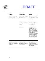
Page 32: ...g roubleshooting roubleshooting roubleshooting roubleshooting Problem Problem Problem Problem Probable Cause Probable Cause Probable Cause Probable Cause Solution Solution Solution Solution The Power...

Page 33: ...r Service see page 31 You receive an error message when configuring the scanner The scanner may not be turned on Verify that the Power ON LED is lit The scanner s serial port connection to your comput...

Page 34: ...for at least 3 milliseconds No RF Power The supplied SCS Diagnostic tag may be used to verify that the scanner is transmitting RF power When held within a few inches of the transmit antenna the LED o...

Page 35: ...i l a b l e 1 InstaScan Scanner Information I n s t a S c a n M o d e l N u m b e r S e r i a l N u m b e r l o c a t e d o n t h e b o t t o m o f s c a n n e r A n y m o d i f i c a t i o n s m a d...

Page 36: ...n f i g u r a t i o n p r o g r a m F o l l o w t h e s e s t e p s t o r e t u r n y o u r s c a n n e r a n d a c c e s s o r i e s f o r s e r v i c e C a r e f u l l y p a c k y o u r s c a n n e...

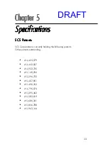
Page 37: ...e following patents Other patents outstanding 4 424 579 4 442 507 4 933 735 5 148 256 5 296 722 5 407 851 5 496 763 4 796 074 5 095 362 5 583 819 5 686 341 5 856 788 5 963 144 Chapter 5 Chapter 5 Chap...

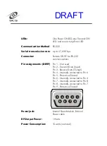
Page 38: ...I n p u t P i n 3 R e c e i v e D a t a O u t p u t P i n 4 I n t e r n a l l y c o n n e c t e d t o P i n 6 P i n 5 P r o t e c t i v e G r o u n d P i n 6 I n t e r n a l l y c o n n e c t e d t o...

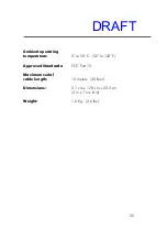
Page 39: ...perature 0 t o 5 0 C 3 2 t o 1 2 2 F Approved Standards F C C P a r t 1 5 Maximum serial cable length 1 0 m e t e r s 3 0 F e e t Dimensions 5 1 c m x 1 7 8 c m x 2 0 3 c m 2 i n x 7 i n x 8 i n Weigh...

Page 40: ...it antenna select bit 5 9 TX_ASEL3 Transmit antenna select bit 3 10 TX_ASEL1 Transmit antenna select bit 1 11 RX ASEL5 Receive antenna select bit 5 12 RX ASEL3 Receive antenna select bit 3 13 RX_ASEL1...

Page 41: ...4 a n d 1 1 a r e t h e h i g h o r d e r b i t s o f t h e h a r d w a r e p i n s t h a t s e l e c t t h e r e c e i v e a n t e n n a B i t 0 i s k e p t i n t e r n a l t o t h e i n t e r r o g...

Page 42: ...n a Q u a n t i t y c o m m a n d 3 D e f a u l t m o d e a u t o m a t i c a l l y c y c l e s t h r o u g h a l l a n t e n n a s T h e i n t e r r o g a t o r w i l l f r e e z e a t a c e r t a i...

Page 43: ...o f t h e W r i t e P e r i p h e r a l O u t p u t s c o m m a n d T h e o u t p u t s a r e c o m p a t i b l e w i t h C M O S l e v e l s Table 5 O u t p u t C h a r a c t e r i s t i c s N o t e...

Page 44: ...z e d o u t p u t o f t h e R F r e c e i v e r R e c e i v e r b l a n k i n g s i g n a l B L A N K W h e n l o w t h e m i c r o c o n t r o l l e r i s i g n o r i n g t h e o u t p u t f r o m t...

Page 45: ...arranty repair any product that has been subjected to any abnormal electrical mechanical or environmental abuse FCC Part 15 Compliance The FCC has established rules that permit the scanner and tag sys...

Page 46: ...w h i l e s p e n d i n g t h e o t h e r 5 0 o f t h e t i m e a t m o r e t h a n 5 a w a y t h e a l l o w e d R F e x p o s u r e l i m i t s w i l l b e s a t i s f i e d O p e r a t o r s s h o...

Page 47: ...4 3 DRAFT...

Reviews: