12
Connecting External Antennas
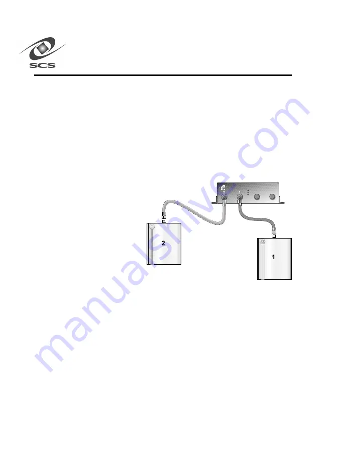
The front panel has two coaxial antenna connectors. Each connector
accommodates a single external antenna. Figure 5 shows the external
antenna connections to the scanner. The S512-C scanner uses one or two
antennas. When looking at the front panel, from left to right, the antenna
ports are numbered “2” and “1” (see Figure 5). If using one antenna, it
should be connected to antenna port “1”, and antenna port “2” should be
terminated with a 50 ohm load.
Figure 5.
Connecting
External Antennas
Warning -- RF
cable connections
should be
tightened to 8
inch pounds.
Over tightened RF cables damage the ports on the antennas and
the S512-C. Loose connections can result in decreased system
performance.
Warning -- Attempting to transmit power to open scanner ports
(i.e. Neither and antenna nor a load is attached to the port) will
will
will
will
will
cause serious damage to the S512-C.
DRAFT
Summary of Contents for INSTASCAN S512-C
Page 47: ...4 3 DRAFT...


